10
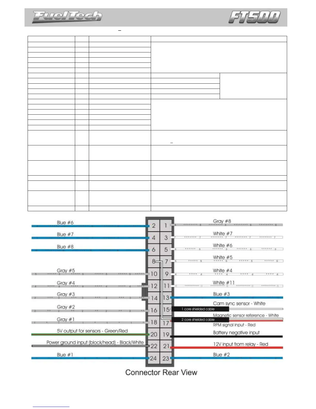
4.1 Harness connections 24 way connector
These outputs are usually used for injector control. When needed,
they can be configured as auxiliary outputs.
These inputs can be set up as
any kind of analog or digital
sensor.
Standard: coolant temperature
Standard: air temperature
These outputs are usually used for ignition control.
When needed, they can be set up as injector outputs or auxiliary
outputs.
By standard, Gray output #8 is used as a tachometer output.
White wire from the
2 core shielded
cable
Magnetic RPM sensor
reference
Connected to the negative wire of the magnetic sensor. When OEM
ECU is reading the sensor in parallel, split this wire with OEM sensor
negative Do not connect when using hall effect sensor.
Red wire from the 1
core shielded cable
Connected to the crank trigger sensor (hall or magnetic) or to the
distributor.
Connect the shield to the sensor shield (when applicable)
White wire from the
1 core shielded
cable
Connected to the cam sync sensor (hall or magnetic)
Use the shield as negative to the sensor
Connected to the pin 87 of the Main Relay.
Connected directly to the battery negative with no seams. Do not
connect this wire to the chassis, engine block or head.
Engine ground (head/block). Connect the three black/white wires
from the harnesses in different points of the engine.
Do not connect it directly to the battery negative.
5V voltage output for TPS, electronic throttle and pedal sensors