41
13.6 Camshaft position sensor
This sensor tells the ECU when the cylinder #1 is reaching its TDC on the compression stroke. With this
information it is possible to control ignition and fuel injection in sequential mode. Installation and alignment of this sensor
are pretty simple. The only requirement is that this sensor is triggered before the crank trigger sensor goes through the
gap on the crank trigger wheel.
Cam sync sensors table
Chevrolet Calibra, Vectra GSi, Ômega 4.1,
Citroën ZX 2.0, Xantia 2.0, Peugeot 306 2.0
16V, Peugeot 405MI
Hyundai Tucson 2.0 16V
Pin 1: 5V (FT green/red wire)
Pin 2: white wire (1 core shielded cable)
Pin 3: shield (1 core shielded cable)
Chevrolet Vectra 16V (97 and on)
Pin 1: shield (1 core shielded cable)
Pin 2: white wire (1 core shielded cable)
Pin 3: 5V (FT green/red wire)
Fiat Marea 5 Cylinders, Chevrolet Astra 16V,
Zafira 16V
Pin 1: 5V (FT green/red wire)
Pin 2: white wire (1 core shielded cable)
Pin 3: shield (1 core shielded cable)
Chevrolet Corsa 16V, Tigra
Pin 15: 5V (FT green/red wire)
Pin 6: white wire (1 core shielded cable)
Pin 17: shield (1 core shielded cable)
Pin A: shield (1 core shielded cable)
Pin B: white wire (1 core shielded cable)
Pin C: 5V (FT green/red wire)
Pin 1: shield (1 core shielded cable)
Pin 2: white wire (1 core shielded cable)
Pin 3: shield (1 core shielded cable)
Pin 1: white wire (1 core shielded cable)
Pin 2: shield (1 core shielded cable)
Pin 1: 5V (FT green/red wire)
Pin 2: white wire (1 core shielded cable)
Pin 3: shield (1 core shielded cable)
Suzuki Hayabusa e Suzuki SRAD
Pin 1: white wire (1 core shielded cable)
Pin 2: shield (1 core shielded cable)
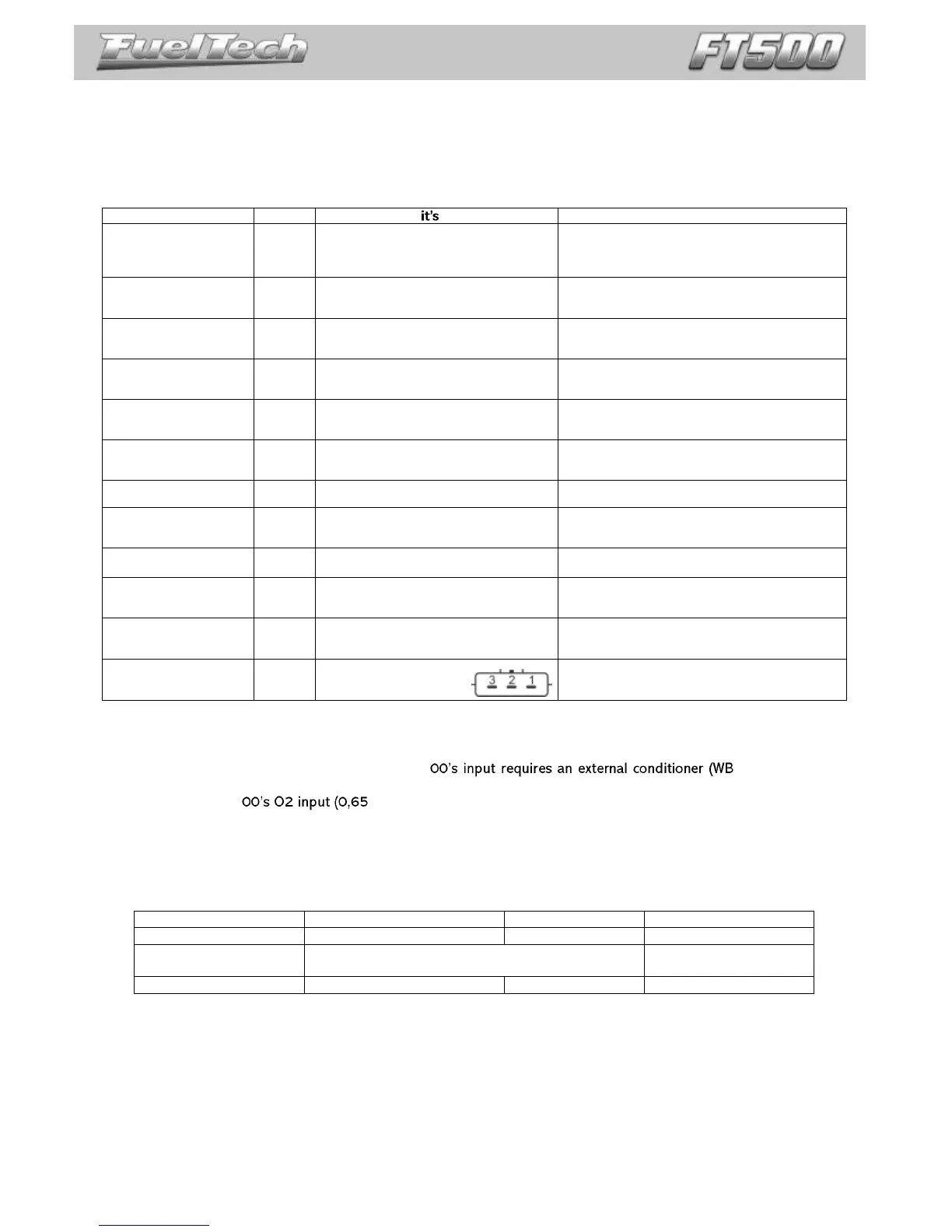
3 wires (close the small
hole with an adhesive)
Pin 1 - black: shield (1 core shielded cable)
Pin 2 - white/red: white wire (1 core shielded cable)
Pin 3 - red: 5V (FT green/red wire)
Fiat engine E-TorQ
1.8 16V
Fiat engine E-TorQ
1.8 16V
Pin 1: shield (1 core shielded cable)
Pin 2: white wire (1 core shielded cable)
Pin 3: 5V (FT green/red wire)
Pin 1: 5V (FT green/red wire)
Pin 2: shield (1 core shielded cable)
Pin 3: white wire (1 core shielded cable)
13.7 O2 sensor
Wideband O2 sensor
The use of wideband lambda sensors on FT5 -O2 Slim or WB-O2
Datalogger). It is important to verify the measurement range of conditioner analog output, as this will be informed during
the configuration of FT5 -1,30λ, 0,65-4,00λ or 0,65 to 9,99λ).
Narrowband O2 sensors
Although less precise than the wideband lambda sensor, narrowband O2 sensors can be connected to the ECU input
for the display of values (in Volts) at the Dashboard and at the Diagnostic Panel. Narrowband O2 sensors usually follow a
standard set of colors, facilitating the wiring. The table below shows the wiring instructions based on the color scheme
generally used for O2 sensor wires:
Switched 12V and ground (connect one wire onto the
12V and the other to ground – there is no polarity)
Battery’s negative terminal
As a general rule, if there are two wires with the same color, one is the switched 12V and the other is the
ground.
After connecting the O2 sensor to the ECU, the O2 sensor input must be set up as guides chapter 16.5.