8-4
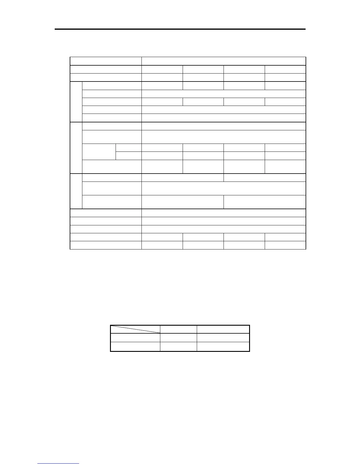
8.1.4 Single-phase 100 V series
FRN_ _ _ _C2S-6, where = U
Item Specifications
Type (FRN_ _ _ _C2S-6U) 0001 0002 0003 0005
Nominal applied motor (HP) *
1
1/8 1/4 1/2 1
Rated capacity (kVA) *
2
0.26 0.53 0.95 1.6
Rated voltage (V) *
3
Three-phase, 200 to 240 V (with AVR function)
Rated current (A) 0.7 1.4 2.5 4.2
Overload capability 150% of rated output current for 1 min or 200% of rated current for 0.5 s
Output Ratings
Rated frequency (Hz) 50 / 60 Hz
Phases, voltage, frequency Single-phase, 100 to 120 V, 50/60 Hz
Voltage and frequency
variations
Voltage: +10 to -10%, Frequency: +5 to -5%
(w/ DCR) 2.2 3.8 6.4 12.0
Rated current
(A) *
4
(w/o DCR) 3.6 5.9 9.5 16.0
Input Ratings
Required power supply
capacity (kVA) *
5
0.3 0.5 0.7 1.3
Braking torque (%) *
6
150 100
DC braking
Starting frequency*
7
: 0.0 to 60.0 Hz, Braking time: 0.0 to 30.0 s,
Braking level: 0 to 100%
Braking
Transistor for
braking resistor
-- Built-in
Applicable safety standards UL508C
Enclosure IP20 (IEC 60529:1989), UL open type (UL50)
Cooling method Natural cooling
Mass (kg) 0.7 0.7 0.8 1.3
Mass (lbs) 1.5 1.5 1.8 2.9
*1 Fuji 4-pole standard motors.
*2 Assuming the rated output voltage as 220 V.
*3 Output voltage cannot exceed the twice of power supply voltage.
*4 Estimated value to apply when the inverter is connected to the power supply of 50 kVA and %X = 5%.
*5 Obtained when a DC Reactor (DCR) is used.
*6 Average braking torque when a motor of no load decelerates from 60 Hz. (It varies with the efficiency of the
motor.)
*7 Effective function only in induction motor drive.
Note: When driven by 100 VAC, the single-phase 100 V series of inverters limit their shaft output and maximum
output torque as listed below. This is to prevent their output voltage from decreasing when load is applied.
Shaft output (%) Maximum torque (%)
w/o DC reactor (DCR) 90 150
w/ DC reactor (DCR) 85 120
Note: A box () in the above table replaces A, C, E, or U depending on the shipping destination.
A: Asia, C: China, E: EC, U: USA

 Loading...


