4-4
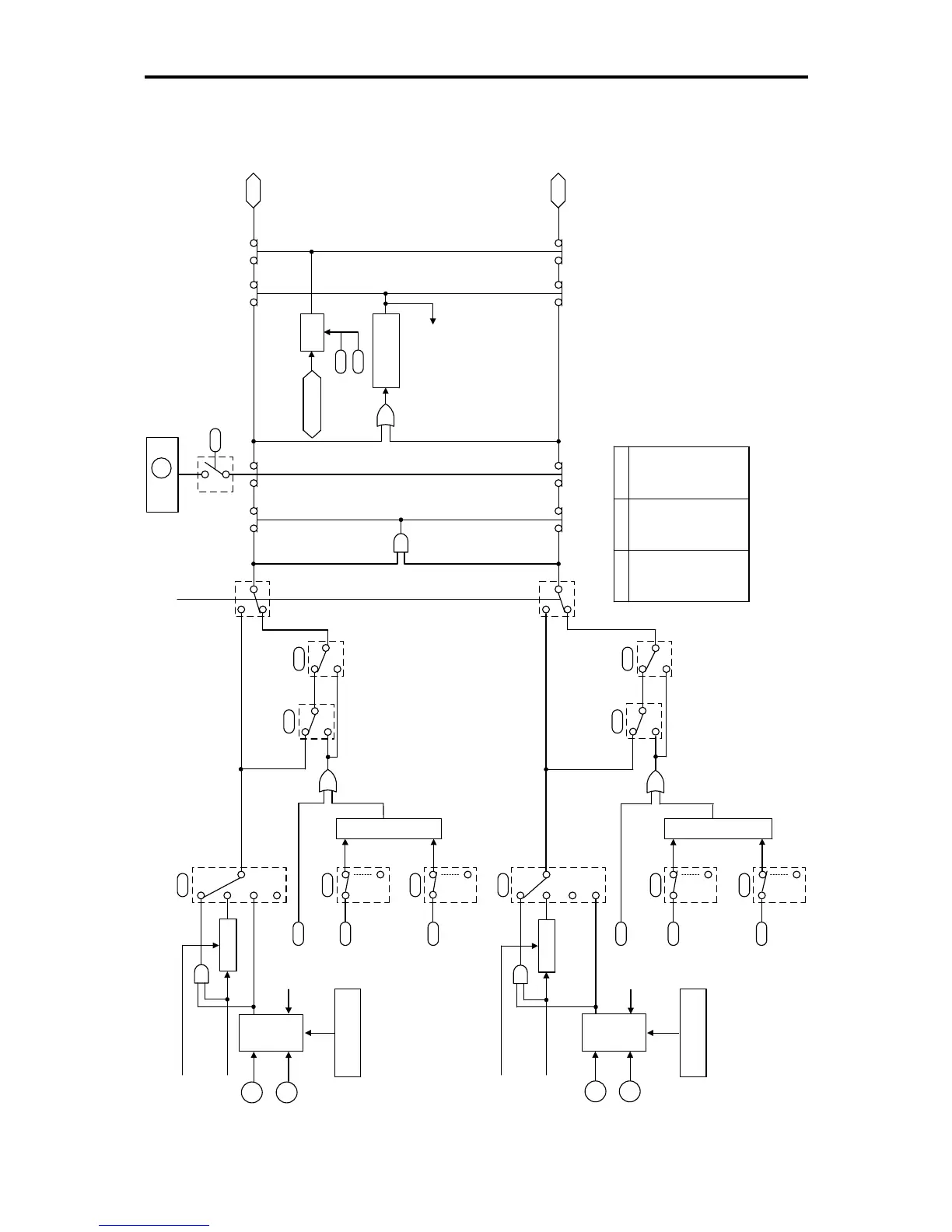
4.3 Drive Command Generator
0
1
2
0,1
2,3
0,1
2,3
bit 13
bit 14
bit 1
FWD
bit 13
bit 14
bit 0
3
0
1
2
3
0,1
0,1
2,3
2,3
REV
S06
S06
S06
F02
E98
E99
F02
E98
E99
S06
S06
S06
H30
H30
y99
y99
F23
F25
Ready for Jogging
(Hold Prohibited)
Hold
RUN
STOP
#
Release
Hold
Hold
(FWD)
(HLD)
Run/Stop
Operation
Run Command
Run Command
Run Command
Hold
[FWD]
[REV]
ON
at 98
ON
at 98
S06 (bit 13, bit 14)
Processor
*
Run/Stop
Operation
Communications
Link
Link Function
for Supporting
Data Input
Enable
Communications Link
(LE)
Priority: STOP Key
ON at 1, 3
H96
Set Frequency
Run
Decision
Start Frequency
Stop Frequency
Timer
(Timer Operation Time)
#
Forcibly
OFF, if
both are
ON.
Ready for Jogging
(Hold Prohibited)
Hold
RUN
STOP
#
Release
Hold
(FWD)
(HLD)
ON
at 99
ON
at 99
S06 (bit 13, bit 14)
Processor
*
Run Command
Run Command
Run Command
[FWD]
[REV]
Communications
Link
Link Function
for Supporting
Data Input
* Truth Table for S06 (bit 13, bit 14) Processor
-:Not assigned
(Outputs the value of the assigned bit)
bit 13 bit 14
Output
ON ON ON
ON OFF OFF
OFF ON OFF
OFF OFF OFF
ON - ON
OFF - OFF
-ONON
-OFFOFF
Note)
The S codes are communication-related function codes.
Refer to the user's manual of RS-485 communication
for details.
Figure 4.2 Drive Command Generator