8-20
8.4.3 Terminal arrangement diagram and screw specifications
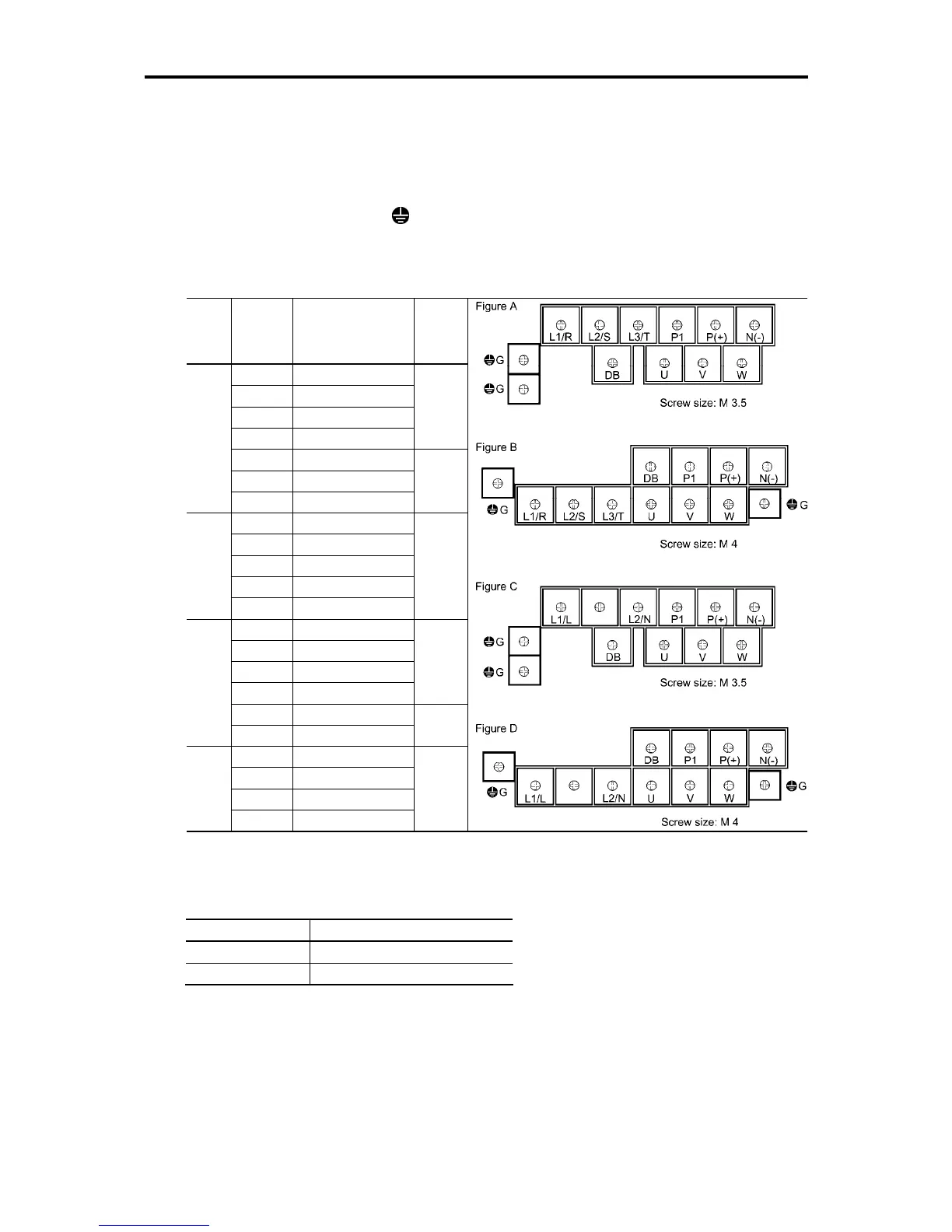
8.4.3.1 Main circuit terminals
The table below shows the main circuit terminal arrangements, screw sizes, and tightening torque.
Note that the terminal arrangements differ according to the inverter types. Two terminals designed for
grounding shown as the symbol,
in Figures A to D make no distinction between a power supply
source (a primary circuit) and a motor (a secondary circuit).
Table 8.1 Main Circuit Terminal Arrangements, Screw Sizes, and Tightening Torque
(0.1 kW to 3.7 kW class (1/8 HP to 5 HP class))
Power
supply
voltage
Applicable
motor
rating
kW (HP)
Inverter type Refer to:
0.1 (1/8) FRN0001C2S-2
0.2 (1/4) FRN0002C2S-2
0.4 (1/2) FRN0004C2S-2
0.75 (1) FRN0006C2S-2
Figure A
1.5 (2) FRN0010C2S-2
2.2 (3) FRN0012C2S-2
Three-
phase
200 V
0.75 (1) FRN0005C2S-6U
Figure C
Notes: 1) A box () in the above table replaces A, C, E, or U depending on the shipping destination.
2) A box () in the above tables replaces S (Basic type) or E (EMC filter built-in type) depending on the
enclosure.
Screw size Tightening torque
M3.5 1.2 N·m (10.6 lb-in)
M4.0 1.8 N·m (15.9 lb-in)

 Loading...


