4-6
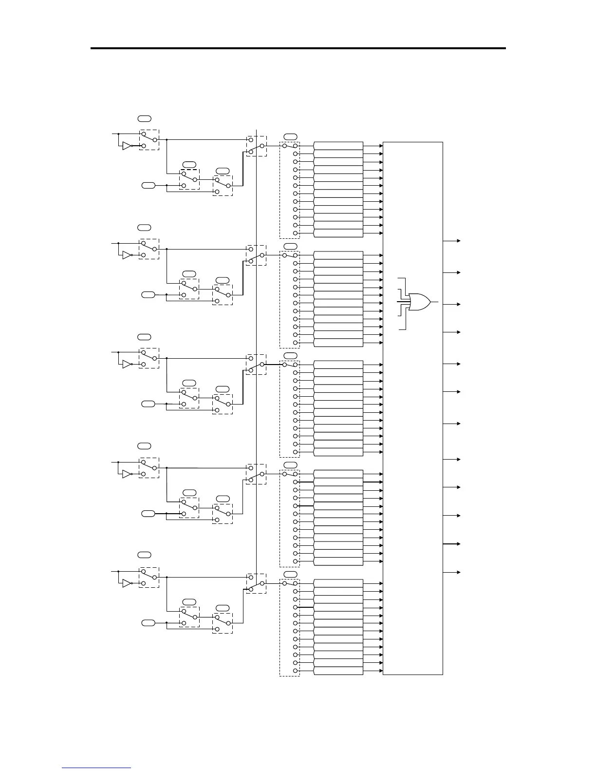
4.4 Terminal Command Decoders
Figures 4.3 (a) through (d) show five types of the terminal command decoder for the digital input signals.
(X1)
(X2)
(X3)
(FWD)
(REV)
SS1 (X1)
SS2 (X1)
SS4 (X1)
RT1 (X1)
1
0
2
3
4
11
12
13
20
E01
21
33
34
IVS (X1)
PID-RST (X1)
PID-HLD (X1)
Hz/PID (X1)
Hz2/Hz1 (X1)
SS8 (X1)
M2/M1 (X1)
DCBRK (X1)
SS1 (X2)
SS2 (X2)
SS4 (X2)
RT1 (X2)
1
0
2
3
4
11
12
13
20
E02
21
33
34
IVS (X2)
PID-RST (X2)
PID-HLD (X2)
Hz/PID (X2)
Hz2/Hz1 (X2)
SS8 (X2)
M2/M1 (X2)
DCBRK (X2)
SS1 (X3)
SS2 (X3)
SS4 (X3)
RT1 (X3)
1
0
2
3
4
11
12
13
20
E03
21
33
34
IVS (X3)
PID-RST (X3)
PID-HLD (X3)
Hz/PID (X3)
Hz2/Hz1 (X3)
SS8 (X3)
M2/M1 (X3)
DCBRK (X3)
SS1 (FWD)
SS2 (FWD)
SS4 (FWD)
RT1 (FWD)
1
0
2
3
4
11
12
13
20
E98
21
33
34
IVS (FWD)
PID-RST (FWD)
PID-HLD (FWD)
Hz/PID (FWD)
Hz2/Hz1 (FWD)
SS8 (FWD)
M2/M1 (FWD)
DCBRK (FWD)
SS1 (REV)
SS2 (REV)
SS4 (REV)
RT1 (REV)
1
0
2
3
4
11
12
13
20
E99
21
33
34
IVS (REV)
PID-RST (REV)
PID-HLD (REV)
Hz/PID (REV)
Hz2/Hz1 (REV)
SS8 (REV)
M2/M1 (REV)
DCBRK (REV)
Enable DC braking
(DCBRK)
Select motor 2/
motor 1
(M2/M1)
[X1]
Normal/Negative Logic Selection
[X1]
Run Command 1
bit 2
0,1
2,3
0,1
2,3
≧1000
<1000
E01
S06
H30
y99
Enable
Communications Link
(LE)
Communications
Link
Link Function
for Supporting
Data Input
[X2]
[X2]
bit 3
0,1
2,3
0,1
2,3
≧1000
<1000
E02
S06
H30
y99
Normal/Negative Logic Selection
Run Command 1
Communications
Link
Link Function
for Supporting
Data Input
[X3]
[X3]
bit 4
0,1
2,3
0,1
2,3
≧1000
<1000
E03
S06
H30
y99
Normal/Negative Logic Selection
Run Command 1
Communications
Link
Link Function
for Supporting
Data Input
[FWD]
[FWD]
bit 13
0,1
2,3
0,1
2,3
≧1000
<1000
E98
S06
H30
y99
Normal/Negative Logic Selection
Run Command 1
Communications
Link
Link Function
for Supporting
Data Input
[REV]
[REV]
bit 14
0,1
2,3
0,1
2,3
≧1000
<1000
E99
S06
H30
y99
Normal/Negative Logic Selection
Run Command 1
Communications
Link
Link Function
for Supporting
Data Input
Notes)
- Each number shown at switches E01 to E03, E98 and
E99 is data in normal logic system.
- The DCBRK (“Enable DC braking”) cannot be used
for negative logic system.
- The S codes are communication-related function codes.
Refer to the user's manual of RS-485 communication for details.
[REV]
[FWD]
[X3]
[X2]
[X1]
The final output
turns ON if one of
signals is ON by
ORing operation,
when E01, E02,
E03, E98, and E99
are set to the same
data.
Switch
Normal/Inverse
Operation
(IVS)
Reset PID Integral
and
Differential
Components
(PID-RST)
Hold PID Integral
Component
(PID-HLD)
Cancel PID Control
(Hz/PID)
Select ACC/DEC
Time
(RT1)
Switch Frequency
Command 2/1
(Hz2/Hz1)
Select Multistep
Frequency
(SS1)
Select Multistep
Frequency
(SS2)
Select Multistep
Frequency
(SS4)
Select Multistep
Frequency
(SS8)
Figure 4.3 (a) Terminal Command Decoder (General)