4.4 Terminal Command Decoders
4-7
Chap. 4 BLOCK DIAGRAMS FOR CONTROL LOGIC
[X1]
[X1]
[X1]
<1000
≧1000
9
24
[X2]
[X2]
[X2]
<1000
≧1000
9
24
[X3]
[X3]
[X3]
<1000
≧1000
9
24
[FWD]
[FWD]
<1000
≧1000
9
24
[REV]
[REV]
<1000
≧1000
9
24
Enable External
Alarm Trip
(THR)
Enable
Communications
Link
(LE)
[REV]
[FWD]
E01
E02
E03
E98
E99
E01
E02
E03
E98
E99
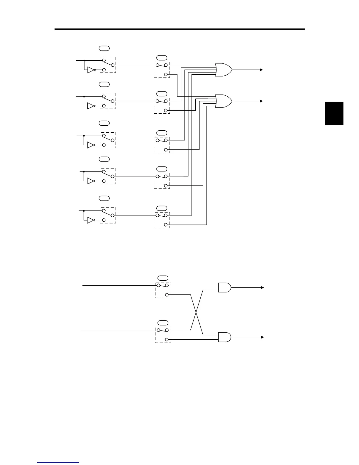
Normal/Negative Logic Selection
Normal/Negative Logic Selection
Normal/Negative Logic Selection
Normal/Negative Logic Selection
Normal/Negative Logic Selection
Note)
Each number shown at switches E01 to
E03, E98 and E99 is data in normal
logic system.
Figure 4.3 (b) Terminal Command Decoder (Terminal Signal Inputs)
98
99
[REV]
[FWD]
98
99
[REV]
[FWD]
Run Forward
(FWD)
Run Reverse
(REV)
E98
E99
Figure 4.3 (c) Terminal Command Decoder (Terminal Signal Input Excluding Negative Logic)