6-4
6.2.1 Recommended wires
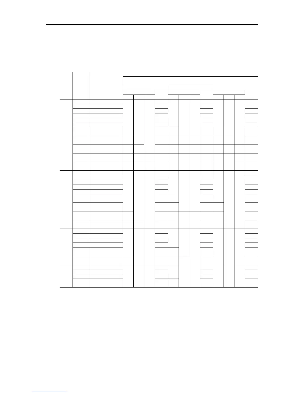
Tables 6.2 and 6.3 list the recommended wires according to the internal temperature of your power
control cabinet.
If the internal temperature of your power control cabinet is 50°C (122°F) or below
Table 6.2 Wire Size (kW, mm
2
ratings) (for main circuit power input and inverter output)
Recommended wire size (mm
2
) at 50°C (122°F) or below
Main circuit power input
[L1/R , L2/S , L3/T] or [L1/L, L2/N]
w/ DC reactor (DCR) w/o DC reactor (DCR)
Inverter output [U , V , W]
Allowable temp.*1 Allowable temp.*1 Allowable temp.*1
Power
supply
voltage
Applicable
motor
rating
(kW)
Inverter type
60°C75°C90°C
Current
(A)
60°C75°C90°C
Current
(A)
60°C 75°C 90°C
Current
(A)
0.1 FRN0001C2S-2 0.57 1.1 0.8
0.2 FRN0002C2S-2 0.93 1.8 1.5
0.4 FRN0004C2S-2 1.6 3.1 3.0
0.75 FRN0006C2S-2 3.0 5.3 5.5
1.5 FRN0010C2S-2 5.7 9.5 8.0
2.2 FRN0012C2S-2 8.3
2.0
(2.5)
13.2
2.0
(2.5)
11
3.7 FRN0020C2S-2
2.0
(2.5)
14.0
5.5
(6)
2.0
(2.5)
2.0
(2.5)
22.2
3.5
(4)
2.0
(2.5)
17
5.5 FRN0025C2S-2
5.5
(6)
2.0
(2.5)
21.1
8
(10)
3.5
(4)
3.5
(4)
31.5
5.5
(6)
3.5
(4)
2.0
(2.5)
25
7.5 FRN0033C2S-2
8
(10)
3.5
(4)
2.0
(2.5)
28.8
14
(16)
5.5
(6)
5.5
(6)
42.7
8
(10)
3.5
(4)
3.5
(4)
33
11 FRN0047C2S-2
14
(16)
5.5
(6)
5.5
(6)
42.2
22
(25)
14
(16)
8
(10)
60.7
14
(16)
8
(10)
5.5
(6)
47
Three-
phase
200 V
15 FRN0060C2S-2
22
(25)
14
(16)
8
(10)
57.6
38
(50)
22
(25)
14
(16)
80.1
22
(25)
14
(16)
8
(10)
60
0.4 FRN0002C2-4 0.85 1.7 1.5
0.75 FRN0004C2-4 1.6 3.1 2.5
1.5 FRN0005C2-4 3.0 5.9 3.7
2.2 FRN0007C2-4 4.4 8.2 5.5
3.7/4.0 FRN0011C2-4 7.3
2.0
(2.5)
13.0 9
5.5 FRN0013C2-4 11.2
3.5
(4)
18.2
2.0
(2.5)
13
7.5 FRN0018C2-4
2.0
(2.5)
15.2
5.5
(6)
2.0
(2.5)
2.0
(2.5)
24.2
3.5
(4)
18
11 FRN0024C2-4
5.5
(6)
2.0
(2.5)
22.2
8
(10)
3.5
(4)
3.5
(4)
34.7
5.5
(6)
2.0
(2.5)
24
Three-
phase
400 V
15 FRN0030C2-4
8
(10)
3.5
(4)
2.0
(2.5)
30.3
14
(16)
5.5
(6)
5.5
(6)
46.1
8
(10)
3.5
(4)
2.0
(2.5)
30
0.1 FRN0001C2-7 1.1 1.8 0.8
0.2 FRN0002C2-7 2.0 3.3 1.5
0.4 FRN0004C2-7 3.5 5.4 3.0
0.75 FRN0006C2-7 6.4
2.0
(2.5)
9.7 5.0
1.5 FRN0010C2-7
2.0
(2.5)
11.7
3.5
(4.0)
2.0
(2.5)
16.4 8.0
Single-
phase
200 V
2.2 FRN0012C2-7
3.5
(4.0)
2.0
(2.5)
2.0
(2.5)
17.5
5.5
(6.0)
3.5
(4.0)
2.0
(2.5)
24.8
2.0
(2.5)
2.0
(2.5)
2.0
(2.5)
11
0.1 FRN0001C2S-6U 2.1 3.5 0.7
0.2 FRN0002C2S-6U 3.8 5.8 1.4
0.4 FRN0003C2S-6U 6.4
2.0
(2.5)
9.4 2.5
Single-
phase
100 V
0.75 FRN0005C2S-6U
2.0
(2.5)
2.0
(2.5)
2.0
(2.5)
12.0
3.5
(4.0)
2.0
(2.5)
2.0
(2.5)
16.0
2.0
(2.5)
2.0
(2.5)
2.0
(2.5)
4.2
*1 Assuming the use of bare wiring (without rack or duct): 600 V class of vinyl-insulated IV wires for 60°C, 600 V class of
polyethylene-insulated HIV wires for 75°C, and 600 V class of polyethylene-insulated cross-link wires for 90°C.
Notes: 1) A box () in the above table replaces A, C, E, or U depending on shipping destination.
2) A box (■) in the above table replaces S (Basic type) or E (EMC filter built-in type) depending on the
enclosure.
3) Values in parentheses ( ) in the above table denote wire sizes for the European version.
If environmental requirements such as power supply voltage and ambient temperature differ
from those listed above, select wires suitable for your system by referring to Table 6.1 and
Appendices, App. F "Allowable Current of Insulated Wires."

 Loading...


