8-22
8.4.3.2 Control circuit terminals
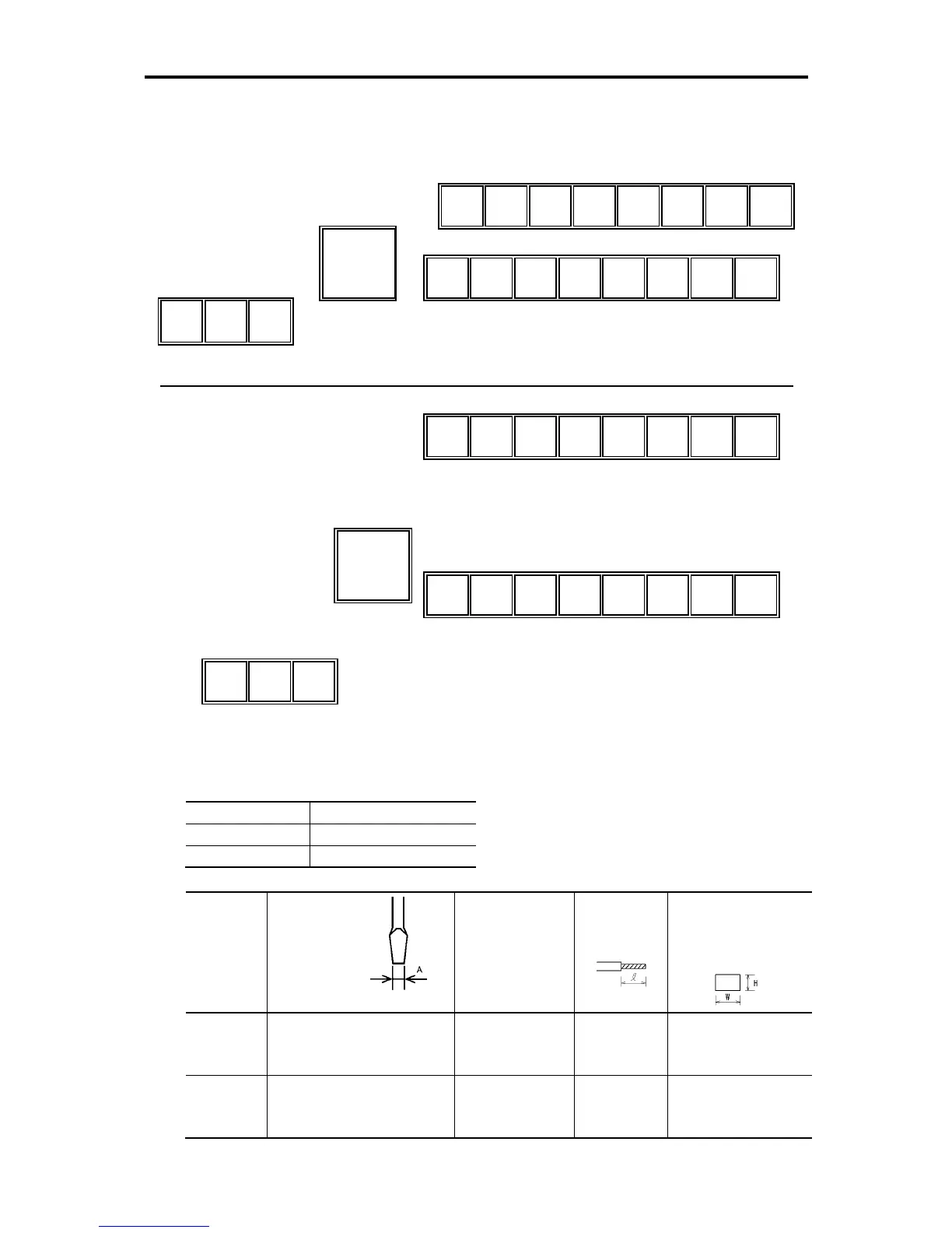
The diagram and table below show the control circuit terminal arrangement, screw sizes, and
tightening torque. They are the same in all FRENIC-Mini models.
Screw size Tightening torque
M2.0 0.2 N·m (1.8 lb-in)
M2.5 0.4 N·m (3.5 lb-in)
Terminal
symbol
Screwdriver
(Shape of tip,
B x A)
Thickness of tip: B
Allowable wire size
Bared wire
length
Ferrule terminal
(see the table below)
Opening dimension in
the terminal block
[30A],
[30B], [30C]
Flat screwdriver
(0.6 x 3.5 mm)
(0.02 x 0.14 inch)
AWG22 to AWG18
(0.34 to 0.75 mm
2
)
6 to 7 mm
(0.24 to 0.28 inch)
2.8 (W) x 1.7 (H) mm
(0.11 (W) x 0.07(H) inch)
Other than
those above
Flat screwdriver
(0.5 x 2.4 mm)
(0.02 x 0.09 inch)
AWG24 to AWG18
(0.25 to 0.75 mm
2
)
5 to 6 mm
(0.2 to 0.24 inch)
1.7 (W) x 1.4 (H) mm
(0.07 (W) x 0.06 (H) inch)
Y1 Y1E FM

 Loading...


