8.4 Terminal Specifications
8-21
Chap. 8 SPECIFICATIONS
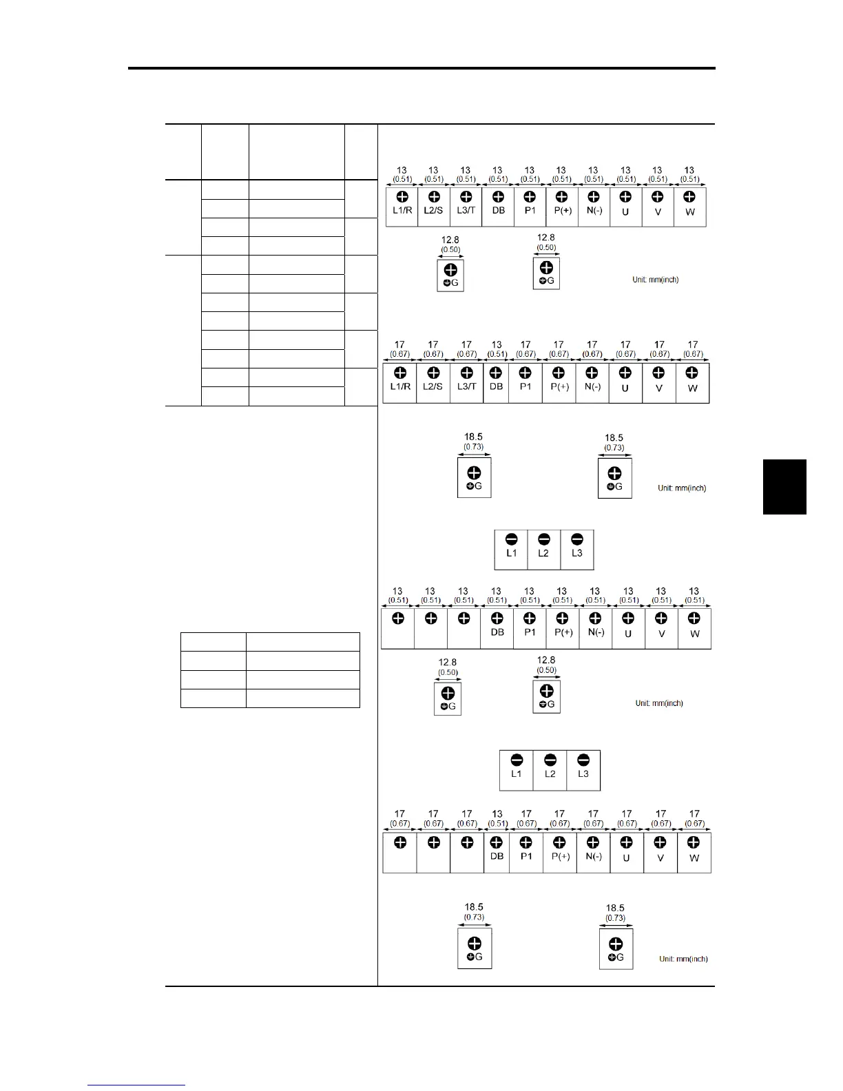
Table 8.2 Main Circuit Terminal Arrangements, Screw Sizes, and Tightening Torque
(5.5 kW to 15 kW class (7.5 HP to 20 HP class))
Power
supply
voltage
Applicable
motor
rating
kW (HP)
Inverter type
Refer
to:
5.5 (7.5) FRN0025C2S-2
7.5 (10) FRN0033C2S-2
Figure
E
11 (15) FRN0047C2S-2
Three-
phase
200 V
15 (20) FRN0060C2S-2
Figure
F
5.5 (7.5) FRN0013C2S-4
7.5 (10) FRN0018C2S-4
Figure
E
11 (15) FRN0024C2S-4
15 (20) FRN0030C2S-4
Figure
F
5.5 (7.5) FRN0013C2E-4
7.5 (10) FRN0018C2E-4
Figure
G
11 (15) FRN0024C2E-4
Three-
phase
400 V
15 (20) FRN0030C2E-4
Figure
H
Screw size Tightening torque
M4 1.8 N・m (15.9 lb-in)
M5 3.0 N・m (26.6 lb-in)
M6 5.8 N・m (51.3 lb-in)
Figure E
Figure F
Figure G
Figure H
Notes: 1) A box () in the above table replaces A, C, E, or U depending on the shipping destination.
2) A box () in the above tables replaces S (Basic type) or E (EMC filter built-in type) depending on the
enclosure.
Screw size: M5
Screw size: M6
Screw size: M6
Source terminal
Screw size: M4
Screw size: M5
Source terminal
Screw size: M4

 Loading...


