8.7 Connection Diagrams
8-37
Chap. 8 SPECIFICATIONS
8.7 Connection Diagrams
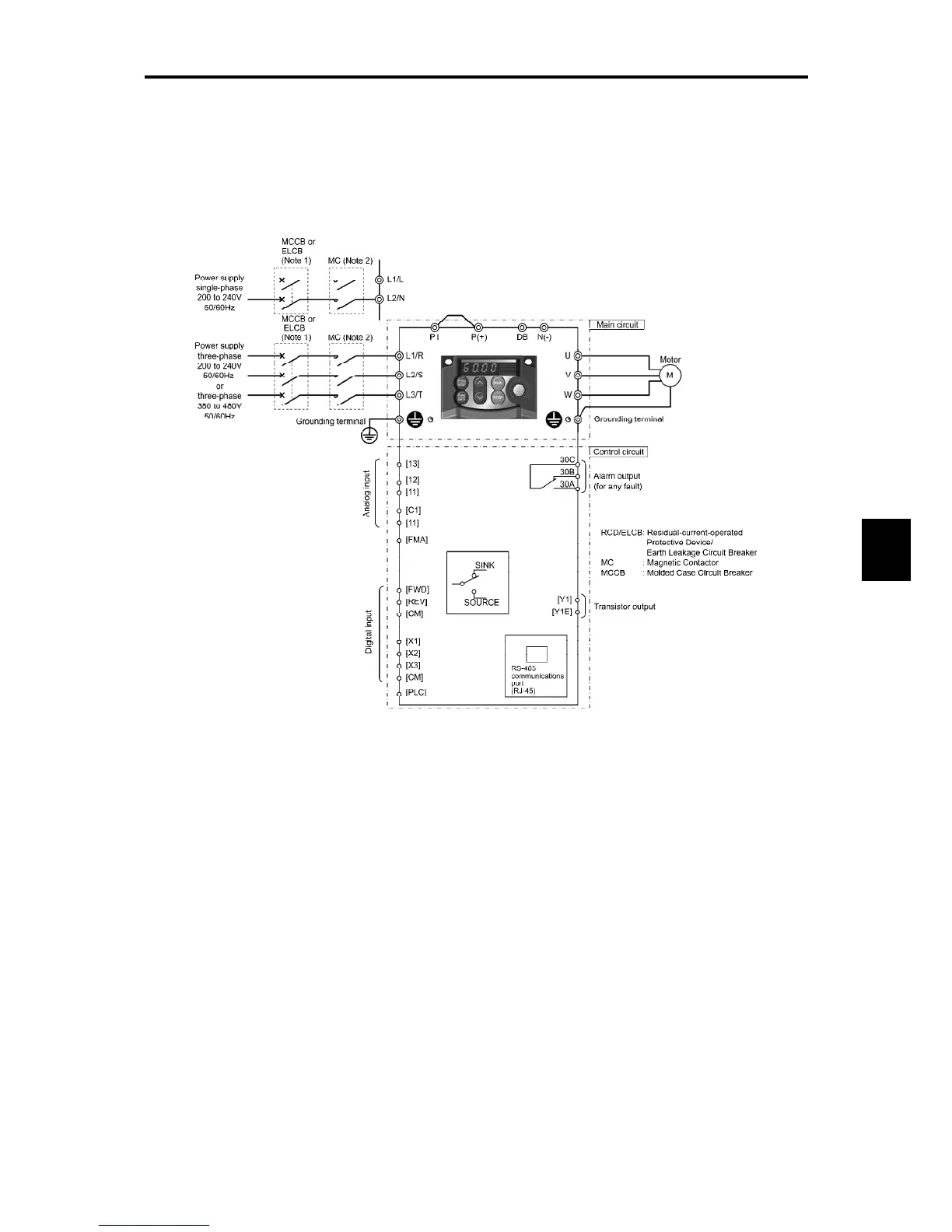
8.7.1 Keypad operation
The connection diagram below shows an example for a keypad operation with the built-in
potentiometer and keys.
(Note 1) Install a recommended molded case circuit breaker (MCCB) or a residual-current-operated protective device (RCD)/earth
leakage circuit breaker (ELCB) (with overcurrent protection) in the primary circuit of the inverter to protect wiring. Do not
use an MCCB or RCD/ELCB whose capacity exceeds the recommended rated current.
(Note 2) A magnetic contactor (MC) should, if necessary, be mounted independent of the MCCB or ELCB to cut off the power fed to
the inverter. Refer to Chapter 6, Section 6.3, [ 1 ] for details. MCs or solenoids that are to be installed close to the inverter
require connecting surge absorbers in parallel to their coils.
* With a built-in terminating resistor
switch

 Loading...


