9-112
PID Display Coefficient and Monitoring
To monitor PID commands and their feedback, define the display coefficient for converting
the contents into easy-to-understand physical quantities such as temperature.
Refer to the descriptions of E40 and E41 for details on display coefficients, and to E43
for details on monitoring.
Gain (J03)
J03 specifies the gain for the PID processor.
- Data setting range: 0.000 to 30.000 (multiple)
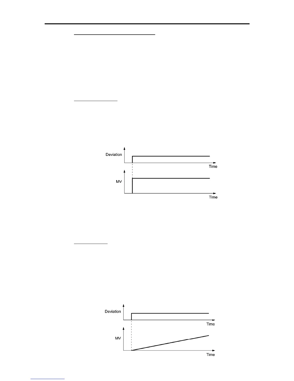
P (Proportional) action
An operation in which the MV (manipulated value: output frequency) is proportional to the
deviation is called P action, which outputs the MV in proportion to deviation. However, the P
action alone cannot eliminate deviation.
Gain is data that determines the system response level against the deviation in P action. An
increase in gain speeds up response, but an excessive gain may oscillate the inverter output. A
decrease in gain delays response, but it stabilizes the inverter output.
Integral time (J04)
J04 specifies the integral time for the PID processor.
- Data setting range: 0.0 to 3600.0 (s)
0.0 means that the integral component is ineffective.
I (Integral) action
An operation that the change rate of an MV (manipulated value: output frequency) is
proportional to the integral value of deviation is called I action, which outputs the MV that
integrates the deviation. Therefore, I action is effective in bringing the feedback amount close
to the commanded value. For the system whose deviation rapidly changes, however, this
action cannot make it react quickly.
The effectiveness of I action is expressed by integral time as parameter, that is J04 data. The
longer the integral time, the slower the response. The reaction to the external disturbance also
becomes slow. The shorter the integral time, the faster the response. Setting too short integral
time, however, makes the inverter output tend to oscillate against the external disturbance.

 Loading...


