Hardware Description CS800 Basic Storage Module
U41842-J-Z125-1-76 73
Dokuschablonen qua19x24 Version 1.1us für FrameMaker V7.x vom 25.03.2010 © cognitas GmbH 2001-2010
1. April 2010 Stand 11:05.09 Pfad: G:\allgemein\CS800\1000500_FTS-Doku\1000502_GettingStartedGuide\GettingStarted.k07
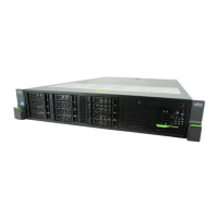
Table 11: DX80 Indicators and Buttons on the Left Side of the Front Panel (with Front Cover)
Item Indicator, Button Description
1 SCU Status LED
(green)
Grows green when the SCU (System Capacitor Unit) is normal.
Blinks green when being charged (for about one minute after
the device power is turned on).
2 ID (Identify) LED
(blue)
Not used with CS800.
3 SAS (DE) Link
LED
(green/orange)
Glows green when link has been established.
Blinks orange when preventive replacement is being performed.
4 SAS (OUT) port Connector for a miniSAS cable
Used to connect the basic DX80 module to a DX80 expansion
module.
5 Act LED
(green)
Glows green when data is being sent and received.
6 RMT port (left)
MNT port (right)
LAN ports (1000Base-T / 100Base-TX / 10Base-T) for device
management
(MNT: Management, RMT: Remote Management)
RJ45 connectors for LAN cables
7 Link LED
(green)
Glows green when the related link has been established.
8 Host Linkup/Fault
LED
(orange)
Glows orange when a fault has been detected in the Fibre
Channel port.
9 Host FC port 0 (left), 1 (right)
Dual LC connectors for Fibre Channel cables connecting the
DX80 with the RX300 S5.
10 PWC port Not used.
11 STS (Status; Unit
Ready/Fault) LED
(green/orange)
Glows green during normal operation.
Glows orange during the post power on initialization phase.
Also glows orange to indicate a fault has been detected.
12 MST (Master)
LED
(green)
Glows green when this unit acts as the master controller
module.
 Loading...


