U41842-J-Z125-1-76 41
Dokuschablonen qua19x24 Version 1.1us für FrameMaker V7.x vom 25.03.2010 © cognitas GmbH 2001-2010
1. April 2010 Stand 11:05.09 Pfad: G:\allgemein\CS800\1000500_FTS-Doku\1000502_GettingStartedGuide\GettingStarted.k06
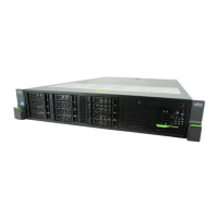
Installing the ETERNUS CS800 Components
Installing the ETERNUS CS800 in a rack consists of the following steps:
1. "Locating the Mounting Position" on page 41
2. "Installing the CS800 System in the Rack" on page 43
3. "Cabling the ETERNUS CS800 System" on page 57
I
See "LAN Cabling" on page 92 and "PTT Cabling (Optional)" on page 93 for
connecting the ETERNUS CS800 system to the network.
Locating the Mounting Position
The ETERNUS CS800 system is designed to fit in a standard 19“ wide rack. It is important
for the chassis installation to locate the hole pattern in the rack rails. You must allow 2 HU
(3.5“) of vertical space for the RX300 S5 server and 2 HU (3.5“) of vertical space for each
DX80 module installed in the rack.
● It is recommended to position the different components of the CS800 system in the
following order:
a) RX300 S5 server on the highest or lowest postion
b) DX80 basic module directly under or above it
c) All DX80 expansion modules directly under or above the DX80 basic module
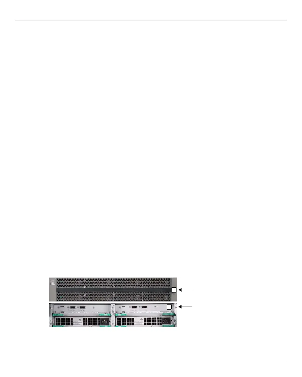
● The DX80 expansion modules are preconfigured and assigned by numbers (1, 2, 3,
etc.) in the factory. This sequence must be observed precisely when they are mounted.
Figure 19: Labels on front and rear of the DX80 expansion module
1
1
Label on the front
Label on the rear
 Loading...


