Hardware Description CS800 Storage Expansion Module
U41842-J-Z125-1-76 75
Dokuschablonen qua19x24 Version 1.1us für FrameMaker V7.x vom 25.03.2010 © cognitas GmbH 2001-2010
1. April 2010 Stand 11:05.09 Pfad: G:\allgemein\CS800\1000500_FTS-Doku\1000502_GettingStartedGuide\GettingStarted.k07
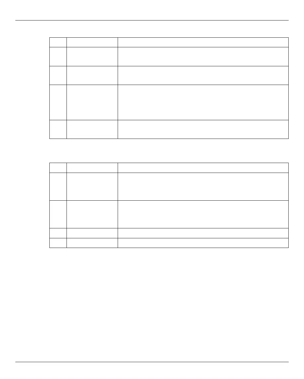
Table 12: DX80 Indicators on the Left Side of the Front Panel (without Front Cover)
Table 13: DX80 Switches on the Left Side of the Front Panel (with Front Cover Removed)
Item Indicator, Button Description
1 POWER LED
(green)
Glows green when the power is turned on.
2 READY LED
(green)
Glows green when device is available for use.
3 FAULT LED
(orange)
Glows orange when an internal device part abnormality has
been detected.
Blinks orange when a device part which needs preventive
replacement has been detected.
4 IDENTIFY LED
(blue)
Not used with CS800.
Item Indicator, Button Description
1 AutoPWR Enables the AC Auto-Link Mode (this function automatically
turns on the linked device once AC power is supplied).
This switch is set to "OFF" as the factory setting.
2 MODE SEL Enables the device power to be turned on via power linkage.
This switch is set to "ON" as the factory setting and should not
be set to "OFF".
3 IP RST Not used in DX80 expansion modules.
4 Power Switch Not used in the DX80 expansion modules.
 Loading...


