U41057-J19-Z146-1-76 July 2004 02–TX150S2–125
Removal/installation routines Power supply
© Siemens Nixdorf Informationssysteme AG 1995 Pfad: P:\02-systemeinheiten\TX150S2\TX150S2-e\TX150S2-e.k04
Replacing power backplane
Requirements
– server has been switched off
– power cords have been disconnected
– left side cover has been removed
– all power supply modules have been removed
The power backplane is mounted on the power supply cage. The power supply
cables are unremovable connected to the power backplane.
Ê Lay the floorstand model on a flat surface with the uncovered side facing
upwards.
This step has to be carried out by two people as the server may
weight up to 28 kg.
Ê Remove the air duct.
Ê Disconnect all power cables of the redundant power supply.
For the cabling see page 02-TX150S2-59.
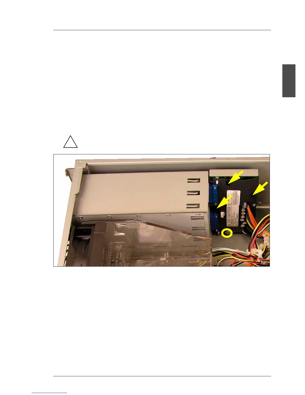
Ê Remove the knurled screw (see circle) which fasten the power backplane to
the power supply cage.
Ê Push the power backplane somewhat downwards to release it from the three
guiding bolts (see arrows).
Ê Take the power backplane out of the server.
The installation of the new power backplane is done in reverse order.
!
 Loading...