Home
Furuno
Marine GPS System
FELCOM 250
Furuno FELCOM 250 Service Manual
4
of 1
of 1 rating
462 pages
Give review
Manual
Specs
To Next Page
To Next Page
To Previous Page
To Previous Page
Loading...
6.2 Settings
6-5
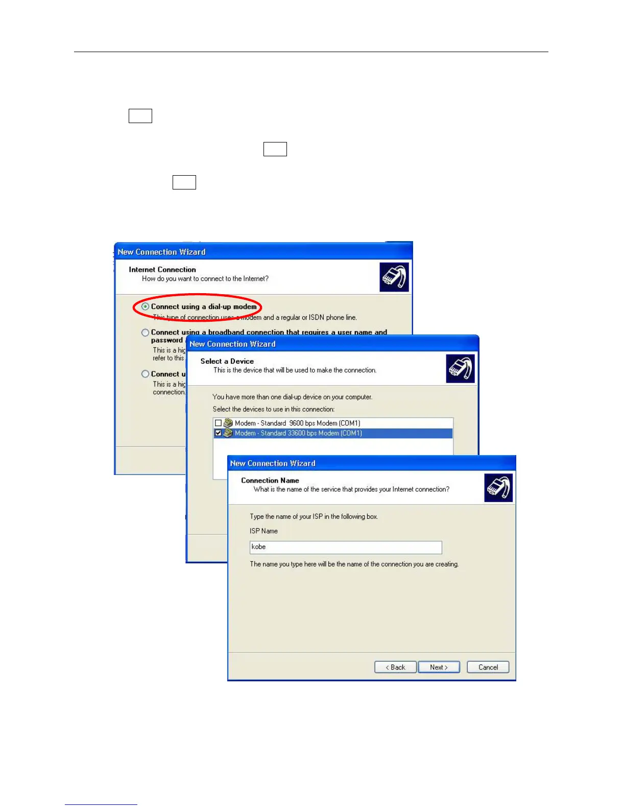
5.
In the next screen, place a tick for “Conn
ect using a dial-up m
odem”, and click
Next
.
6.
The screen “Select a device” will be
displayed. Select “Modem – S
tandard 33600
bps modem” only
, and click
Next
.
7.
In the screen “Connection Name”, enter
the “ISP
Name” for the target connection,
and click
Next
.
203
205
Table of Contents
Default Chapter
43
Table of Contents
43
Check List
61
Installations
68
Operations
70
Communication Unit
71
Maintenance
73
Settings
75
Incoming Indicator
77
Board Replacement
79
Menu Tree
80
Handset Setup List
84
Analog Device Setup List
84
Chapter 1 Overview
85
System Configuration
85
Overview of the Fleet Broad Band
87
Satellite Coverage
87
Ground Facilities
88
Registration
90
Data Network
90
Service
91
Service Types
91
Example Communication Rates
92
Example Selection of the Services
93
Service Description
93
Standard IP Data Service
93
Streaming IP Data Service
93
Circuit-Switched Data Service (Circuit Switching Service)
94
Voice and Message Service
94
Service Contract
96
Network Connection
98
Have the Web MMI for FELCOM-250/500 Displayed
100
Overview
100
Have the Web MMI Displayed
101
Chapter 2. Handling Password
105
SIM Password (PIN Code)
105
Enter the PIN Code
105
Handling the SIM Card
108
PIN Code and PUK Code
108
Change the PIN Code
109
OTA Settings
110
Administrator's Mode and Service Mode
111
Call the Administrator's Mode
111
Call the Service Mode
113
SMS Password
114
Handling the SMS Password
114
Enter the SMS Menu Upon the Web MMI
114
Enter the SMS Menu for the Handset
115
Changing the SMS Password
115
Handling the Password
116
List of Passwords
116
The Procedure for When You Have Forgotten the Password
117
The Procedure for When You Have Forgotten the Operation Password for When You Are to Connect to / Disconnect from WAN
118
The Procedure for When You Have Forgotten the Password
118
The Procedure for When You Have Forgotten the PIN Code
118
Chapter 3. Menu Tree
119
Web MMI
119
The Structure of the Web MMI
119
Administrator's Mode
120
Service Mode
120
Users' Mode
120
Web MMI Menu
120
Handset
136
The Structure of the Handset Screen
136
Chapter 4. Settings for TEL/FAX
147
Overview
147
Settings on the Web MMI
147
Settings on the Handset
148
Settings for the Analog Devices
148
Handling the Service Types
149
Overview of the Settings
150
Settings for Analog Port: TEL/FAX
153
Registering the Handsets in the SIP Server
156
Web MMI: Confirming the Automatic Allocation
156
Web MMI: Registering in the SIP Server
158
Delete the Registered Data
160
Edit the Registered Data
160
Sort the Registered Data
160
Handset: Register Terminal Number and Password
161
Confirm the Other Settings in the SIP Menu
164
Proxy Server
164
S/L Port
164
Expire Time
165
RTP Port
165
Setting the Incoming Routing
166
Setup Example
168
Setting for the Call Limit
171
Group Registration for Extension Calls: Group
172
Setting for the Incoming Indicator
174
Registering the Contacts
175
Register the Contact from the Web MMI
175
Registering the Contact from the Handset Screen
177
Setting for the Analog Phone: FC755D1
179
Setting for FAX: FAX-2810/2820
180
ECM ON/OFF Setting
180
MODEM Settings
181
Initializing EEPROM
182
Print out the WSW Setup Value
183
Chapter 5. WAN Settings
184
WAN Settings
184
Overview
184
WAN Settings
185
Add Connection: Add Streaming IP Data
185
Edit: Editing the Services
187
Settings: WAN Settings
187
Connecting with WAN
189
Connecting with WAN from a
189
Connecting to WAN from the Handset
192
Diagnostics
194
Response Example
195
Enter "Google.co.jp" into the Ping Field
195
Enter "Google.co.jp" into the Nslookup Field
196
Entering Google.co.jp into Ping
197
Entering Google.co.jp into Nslookup
198
Chapter 6. UDI/RDI Communication
200
Overview
200
Settings
201
Install the Standard Modem into the PC
201
Settings for the Dial-Up Connection
203
Settings for Incoming Connections
206
Settings for the Communication Unit
210
Connecting to the Network Using UDI
211
Chapter 7. LAN Settings
212
LAN IP Address
212
Own IP Address
212
IP Address
212
Subnet Mask
212
DHCP Server
214
DHCP Server: Use, Unuse
214
Lease Information
215
Confirm the IP Address
216
Using Static IP Addresses
218
Routing
221
Destination
222
Gateway
222
Metric
222
Rip
223
Rx RIP from LAN
223
Tx RIP to LAN
223
Vrrp
224
Enable/Disable
225
IP Address
225
Name
225
Priorty (1 - 254)
225
Vrrp
225
VRRP Tx Interval
225
Preempt Mode
226
Status
226
Chapter 8. Security Settings
227
Security Settings
227
Firewall
227
Do Not Respond to Ping from WAN
227
Prohibit the Routing of NBT & Microsoft
227
Refuse Demand of IDNET
227
Prohibit Windows-Update
228
IP Filter
228
DMZ (Demilitarized Zone)
228
IP Filter Settings
228
IP Filter List
229
IP Filter List Setting
229
Upnp (Universal Plug & Play)
229
Example of Setting IP Filter
231
Priority Setting
231
VPN Pass-Through
235
Chapter 9. Parts Location
236
Communication Unit: FB-2000
236
Handset: FB-8000
244
Incoming Indicator: FB-3000
246
Antenna Unit: FB-1500
248
Antenna Unit: FB-1500(1/2
248
Antenna Unit: FB-1500(2/2
248
Antenna Unit: FB-1250(1/2
259
Antenna Unit: FB-1250(2/2
260
Chapter 10. Maintenance
269
Overview
269
Power on Sequence
269
The Structure of the Web MMI
270
User Authentication Area: Admin Login
270
Model Name Display: FELCOM-500
271
Self Vessel Position/Date/Time Display
271
Signal Strength Display
271
Alarm Display
272
Status Monitor
273
Overview of the Status Monitor
273
Main -> Status Monitor Screen Upon the Web MMI
273
The Handset Idle Screen
273
Tracking Status
274
Channel
274
Satellite
274
Status
275
Antenna Elevation
276
Signal Strength
276
Ship Position Information
276
Latitude
276
Longitude
276
Using GPS
276
Error Information
277
Error
277
Warning
277
Communication Status
278
Data Connection
278
Standard Data
278
Voice & Fax
278
Streaming Data
279
Temperature Information
279
Hpa
279
Modem
279
System Information
280
Terminal Information
280
Imei
280
Imsi
281
Modem Information
281
CPU Version
281
DSP1 Version
281
DSP2 Version
282
DSP3 Version
282
FPGA Version
282
HUB Information
282
Kernel Version
282
Maintenance Version
282
Software Version
282
ATB Information
283
Hardware Type
283
Hardware Version
283
Product Data
283
Software Version
283
Hardware Version
284
Product Year/Week
284
Production Type
284
Revision
284
Hpa Information
284
Information
285
Basic/Gps (NMEA Port)
285
Basic/Analog Ports Port 1
285
Basic/Incoming Indicator
286
Basic/Serial Port
286
Network/Lan
286
Network/Wan
286
Selftest
287
Executing a Selftest
287
Contents of the Selftest
289
Ade
289
Bde
289
Error Messages for the Selftest
290
Ade
290
Bde
291
Self Test for the Handsets
292
Service
293
Ade
293
T.receiver
293
Free Command and ASK Line Monitor
294
Bde
295
Poe Feeding
295
PLL Information
296
Gain & ATT Information
297
Tx Att
297
Demodulator Gain
298
Rx Att
298
Echo Canceller
299
Extension (Only Analog Phone): Analog Port 1 to Analog Port 4
299
Outside Call
300
Restart
300
LED and DIP Switch for the Communication Unit
301
The Panel LED for the Communication Unit
301
Transitions of the Status LED for When the Power Is Turned
301
LAN Port
302
Board LED and DIP Switch for the Communication Unit
303
POWER Board (16P0266)
303
MODEM Board (16P0274)
304
HUB Board LED
306
Checking the Incoming Indicator: FB-3000
308
Lan Led
309
Initializing the Incoming Indicator
309
Initializing
310
Initializing the Communication Unit
310
Executing Initialization from the Web MMI
310
Reset the Hardware of the Communication Unit
311
Items Initialized in the Communication Unit
312
Initializing the Handset
313
Executing the Initialization Process from the Handset Menu
313
Reboot the Handset
313
Items Initialized in the Handset
314
Reset the Handset Hardware
314
Initializing the Incoming Indicator
315
Reboot the Software
315
Reset the Hardware
315
Communication Unit: FB-2000
316
Chapter 11. Block Description
316
If: 16P0275
317
IF Transmitting Circuit
318
IF Receiving Circuit
319
ASK (Amplitude Shift Keying)
320
Modem: 16P0274
321
Hub: 16P0273
323
Power: 16P0226
325
Adjusted Parts
326
Other Specifications
326
Output Specifications
326
Panel: 16P0227
327
Reset SW
327
Sim
327
Handset: FB-8000
328
Incoming Indicator: FB-3000
329
Antenna Unit: FB-1500/1250
330
Overview
330
The Functions for the Major Module
330
Transmitting and Receiving Circuit
331
Satellite Acquire Sequence
335
Outline of the Sequence for Capturing the Satellite
336
Command
337
Chapter 12. Updating the Software
338
Updating the Communication Unit Software
338
Overview
338
Software Update Procedure
339
Software File
340
Confirming the Software Version
342
Modem, HUB
342
Preparing for the Updating Process
344
Connection for the Updating
344
Install Java
344
Set DHCP to "Use
344
Updating Comm Unit Software Using Two LAN Ports
346
Step-1. PC Network Connection Settings
346
Step-2. Open the Felcomupdate.jar File
347
Step-3. Select "Comm Unit", and Start the Updating Process
348
Updating the Comm Unit Software Using a Single LAN Port
349
Step-1. PC Network Connection Settings
349
Step-2. Open the Felcomupdate.jar File
350
Step-3. Select "Comm Unit", and Start the Updating Process
350
Updating the Software for the Handset and the Incoming Indicator
351
Step-1. PC Network Connection Settings
351
Step-2. Open the Felcomupdate.jar File
352
Step-3. Select "Handset" or "Incoming Indicator", and Start Updating
352
BDE Software Updating Tool
353
When Updating Comm Unit
353
When Updating the Handset
356
When Updating the Incoming Indicator
358
Handling the Software Updating Tool
359
Radio Button
359
Setting
359
Update
359
Device Seach
360
Log
360
Select the Files Unnecessary to be Updated (Reference)
361
Confirm the XXX.cfg File
361
Updating the Software for the Antenna Unit
364
ATB and HPA Software Folders
364
ATB Software Folder
364
HPA Software Folders
364
The Updating Procedure
365
Chapter 13. Q&A
368
Q1. What Is the Difference between FELCOM-500 and FELCOM-250
368
Q2. Is the les the same with the Conventional One
368
Q3. Are Several Different Services Available Concurrently
368
Q4. will Several Sets of Phone Numbers be Allocated
368
Q5. Where Does TA Connect to During ISDN Communication
368
Q6. Please Describe the Communication Rate
368
Q7. Is Mailing Software Attached to Windows
368
(Such as Outlook Express, Etc.) Available
368
Q8. Is the Dedicated Line Service Available
369
Q9. What Is a SIM Card
369
Q10. Can the SIM Card be Used by Other FB Terminals
369
Q11. Where Can We Purchase the SIM Card
369
The PIN Code Is Blocked
369
Q13. What Is Stored in the SIM Card
369
Q14. I Cannot Access the Internet
369
Q15. Even if I Try to Connect with Streaming IP Data
369
Q16. Is There a Specific Direction Specified for Installing the Antenna
369
Q17. Can I Shorten the Antenna Coaxial Cable
370
Q18. Can I Use Inmarsat B or Fleet 77 Antenna Coaxial Cable
370
Is the Antenna Installation Pitch the same
370
Q19. Can I also Use the Conventional Analog Devices
370
Q20. Can I Establish Parallel Connection Using Analog Phone
370
Q21. Are External Input Signals such as Gyro or GPS Required
370
Q22. Please Describe the Specifications
370
Q23. Can We Substitute the LAN Cable with a MP-XX Cable
370
Q24. Can I Make the Settings for the Buzzer Sound
371
Q25. What Is L-Band out Used for
371
Q26. Which SW HUB with What Specification Is Available
371
Q27. Is There any Power Switch for the Handset and the Incoming Indicator
371
Q28. the System Rejects the Password for Administrator's Mode
371
Q29. Is There any Method to Save the System Information
371
Q30. the Elevation Angle for Fleet 77 and FB Are Different
371
Q31. Is It Possible to Apply Restrictions Onto the Phone Calls
371
Q32. Is It Possible to Apply Restrictions Onto
372
Q33. Is There any Way I Can Save the System Log in the
372
Q34. Is There any Specific Range of IP Addresses Available
372
Q35. Is There any Way to Allocate a Static IP Address
372
Q36. What Value Is the Normal Signal Strength
372
Q37. no Communication
372
Q38. What Would Happen if the GPS Data Is Interrupted
373
Q39. the Ready LED Is Blinking at an Interval of 1 Second
373
Q40. Is There any Way to Restore the Settings to Factory Settings
373
Q41. What Do I Have to be Note about When Replacing Boards
373
Q42. Where Is the AZ Direction of the Antenna Displayed
373
Q43. Where Can I Make the Settings for the Global IP Address
373
Q44. What Would Happen if Antenna Blocking Occurs
374
Q45. the Software for the Communication Unit Does Not Get Updated
374
Q46. Is There any Way for Not Updating the Software
374
Q47. the Software Updating Tool Screen Does Not Get Displayed
374
Q48. Is There any Way to Confirm the Transmission
374
Q49. Is It Possible Not to Have Missed Calls or
374
SMS Incoming Messages Not Displayed
374
Q50. What Does the "P" Displayed During Data Connection
374
Q51. Method for Creating a LAN Cable
375
Q52. Noise Interference from FELCOM-500 to the Radio
376
Q53. the Patch Antenna of FELCOM-500 Is Moving up and down
379
Appendix 1. NMEA Port
381
AP1.1 Monitoring the GPS Data
381
AP1.1.1 Monitoring the GPS Data
381
AP1.2 Input Specifications
382
AP1.2.1 NMEA Interface
382
AP1.2.2 List of I/O Sentences
382
AP1.2.3 Handling Input Data
383
Appendix 2. Message List
384
AP2.1 Overview
384
Web MMI
384
Handset Screen
385
AP2.2 Message List
386
AP2.3 Log Operations
401
AP2.3.1 Saving the Log in the PC
401
AP2.3.2 Forward the System Log
403
Appendix 3. Specifications
405
Ap3.1 Felcom-500
405
Ap3.2 Felcom-250
407
Appendix 4. Abbreviations
409
SIM Card (Subscriber Identity Module Card)
409
PIN Code (Personal Identity Number)
409
PUK Code (Personal Unlock Key)
409
Imei
409
OTA (over the Air)
409
ADE (above Deck Equipment)
410
BDE (below Deck Equipment)
410
Apac
410
Amer
410
Emea
410
CS (Circuit Switching)
410
PS (Packet Switching)
410
SMS (Short Message Service)
410
LAN (Local Area Network)
410
WAN (Wide Area Network)
411
Streaming
411
Standard Data
411
URL (Uniform Resource Locator)
411
UDI (Unrestricted Digital Information)
411
RDI (Restricted Digital Information)
412
Khz Audio
412
AMBE (Advanced Multi-Band Excitation)
412
DSP (Digital Signal Processor)
412
C/No
412
RSSI (Received Signal Strength Indicator)
412
Poe
413
APN (Access Point Name)
413
Gateway
413
VPN (Virtual Private Network)
414
Qos (Quality of Service)
414
Ping
414
Nslookup
414
OSI (Open Systems Interconnection) Reference Model
415
MAC Address (Media Access Control Address)
415
IP Address
416
UDP (User Datagram Protocol)
417
Port Number
419
Browser
419
DHCP (Dynamic Host Configuration Protocol)
420
DNS (Domain Name System)
420
DMZ (Demilitarized Zone)
420
Firewall
421
FTP (File Transfer Protocol)
421
Ipsec (Security Architecture for Internet Protocol)
421
ICMP (Internet Control Message Protocol)
421
Ident(Identification Protocol)
421
IP Filter
422
Microsoft DS (Microsoft Directory Service)
422
Metric
422
Nbt(Netbios over TCP/IP)
422
NTP (Network Time Protocol)
422
PPTP (Point-To-Point Tunneling Protocol)
422
Quick Time
422
RIP (Routing Information Protocol)
423
RTP (Real-Time Transport Protocol)
423
Real Player
423
Routing
423
SIP (Session Initiation Protocol)
423
SIP Server
423
Upnp (Universal Plug and Play)
424
VRRP (Virtual Router Redundancy Protocol)
424
Windows Media Player
424
Reference-1) List of Port Numbers
425
Reference-2) List of Protocol Numbers
435
Other manuals for Furuno FELCOM 250
Operator's Manual
190 pages
Installation Manual
66 pages
4
Based on 1 rating
Ask a question
Give review
Questions and Answers:
Need help?
Do you have a question about the Furuno FELCOM 250 and is the answer not in the manual?
Ask a question
Furuno FELCOM 250 Specifications
General
Brand
Furuno
Model
FELCOM 250
Category
Marine GPS System
Language
English
Related product manuals
Furuno FELCOM 12
182 pages
Furuno FELCOM 500
462 pages
Furuno GP-32
88 pages
Furuno SCX-21
32 pages
Furuno GP-1650
94 pages
Furuno GD-3300
137 pages
Furuno GP-7000F
142 pages
Furuno GP-1850F
110 pages
Furuno GP-1850W
44 pages
Furuno NAVNET 1734C
247 pages
Furuno LC-90 Mark-II
2 pages
Furuno C-MAP NT GP-1650
94 pages