10.6 Service
10-29
10.6.2.3 Gain & ATT information
The transmitting output ATT and receiving input ATT for the IF board, and the receiving
gain (AGC) are displayed.
1. TX ATT
Every time the power is turned on, the coaxial cable between ADE and BDE is being
calibrated so that communication can be ensured at the transmission output level (EIRP)
specified by the BGAN network. Calibration will be executed for 11 points for each 3.5
MHz.
The required TX ATT value is the TX ATT value for when the output level is set to the
maximum level (EIRP).
Note that the TX ATT displayed value displayed after calibration is not fixed.
The transmitting ATT value can be confirmed via “TX ATT” in “BDE” for the
FELCOM-250/500 Web MMI Service menu.
Reference)
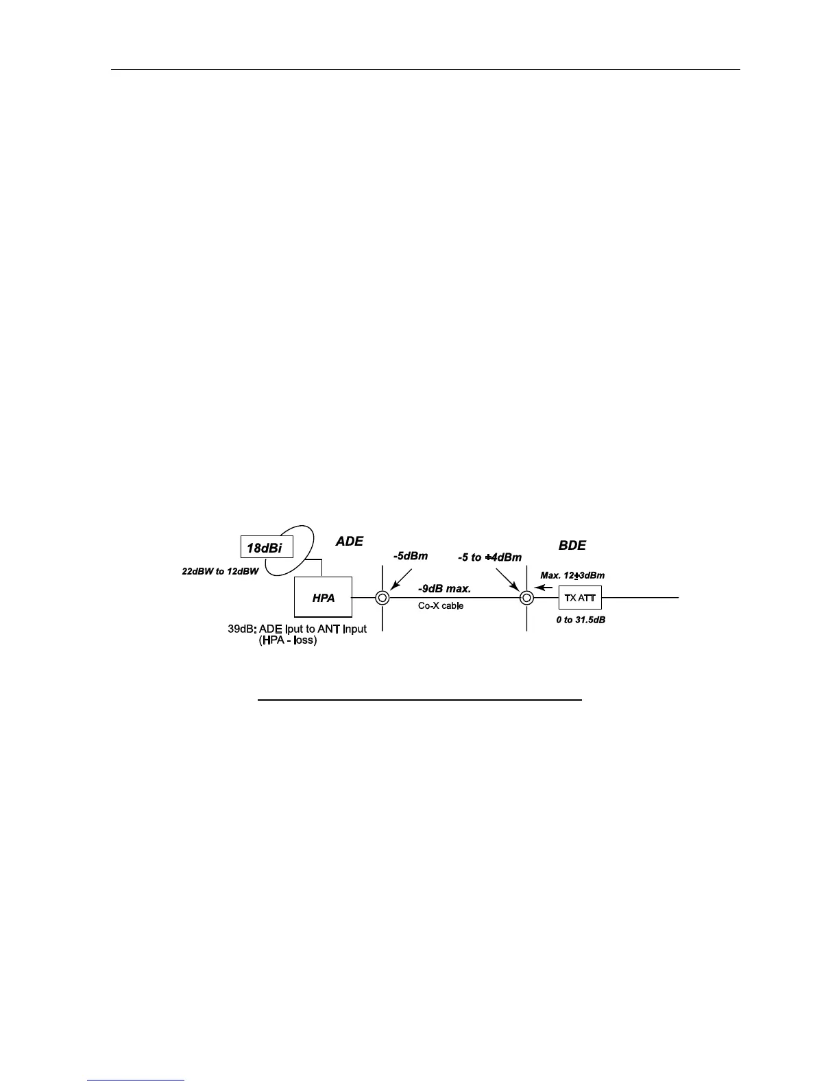
The design is established based on the assumption that the Antenna coaxial cable loss
will be within the range of -9 to -2 dB.
In the FELCOM-500(Class-8), the assumed range for EIPR is 22 to 12 dBW. TX ATT
can be set up between the range of 0 to 31.5 dB, 0.5 dB setp, and the TX ATT setting
will be made so that the EIRP will take the specified value.
Fig. 10.6.2 The arrangement of Tx ATT and Tx level
 Loading...