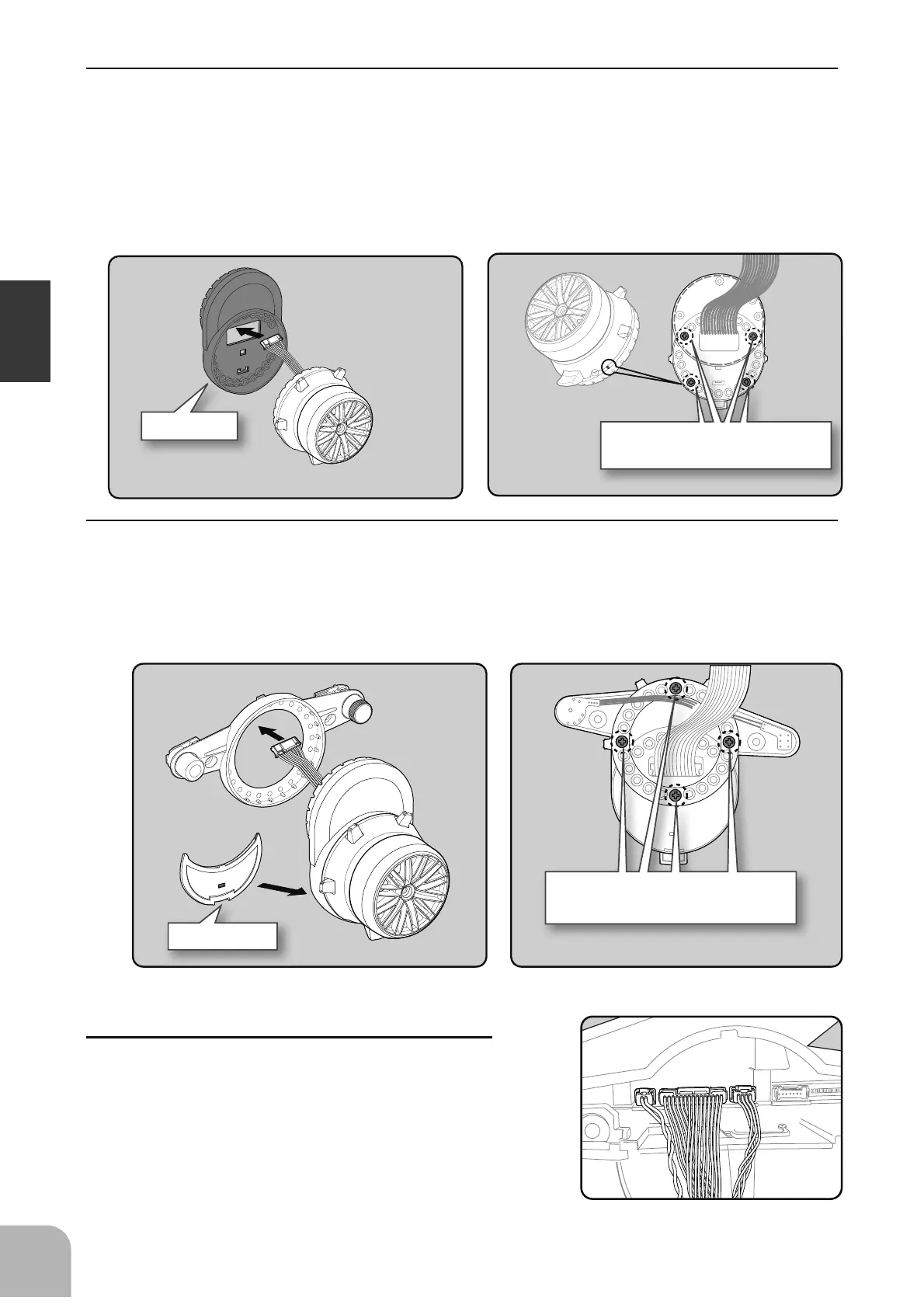
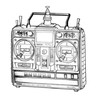
APA rear cover
Switch unit and APA mounting screws
(2.6x8mm tapping screws)
Adapter APA
Wheel unit and APA mounting
screws (2.5x19mm tapping screws)
Marking
26
Before Using
7
Install the assembled steering wheel unit to the
transmitter body.
- From left to right, the order is two-pin connector (PS3), 15
pin connector (wheel unit), four-pin connector (DL1/PS6).
6
Using a Phillips screwdriver, fasten the switch unit and APA. Use the 2.6x8mm tapping
screws in the accessories bag. Next, install the APA rear cover. Be careful that the length of
the screws is correct.
- The 2.6x8 tapping screws are in the accessory bag.
5
Pass the wiring from the steering wheel unit through the hole in the APA, as shown in the
figure. Using a Phillips screwdriver, fasten the wheel unit and APA at the desired angle us-
ing the 2.6x19 tapping screws.
- - Be careful that the screw length is correct. Be cautious that the wiring does not get pinched.
- The 2.6x19 tapping screws in the accessory bag.
- The angle can be adjusted, but check the marking point on the wheel unit and install the screws.
- Screws can be installed at four places, but installation at four sites may be impossible due to the wheel unit
mounting angle.