EasyManuals Logo

GE Dash 4000 Service Manual

GE Dash 4000
282 pages
To Next Page IconTo Next Page
To Previous Page IconTo Previous Page
Page #192 background imageLoading...
Page #192 background image
Field replaceable units: Replace main unit parts
7-46 Dash 3000/4000/5000 2000966-542D
5. Unscrew the thumb screw anchoring the writer cable to the CPU
assembly and disconnect the flex cable from the CPU/battery housing
assembly.
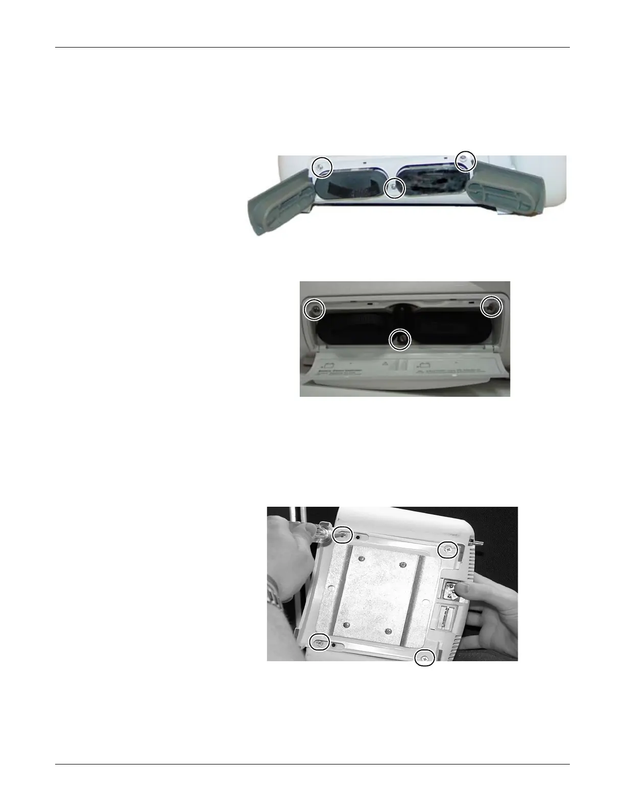
6. Remove the three screws anchoring the battery door assembly to the
rear housing. Remove the battery door assembly.
7. If replacing the battery door only, install the new door and
reassemble the patient monitor. Otherwise, continue with the next
step.
8. Remove the four panhead screws anchoring the CPU/battery housing
assembly to the frame. These screws are attached at the bottom of
the unit.
Screws holding battery door.
581B
895A
517A

Table of Contents

Other manuals for GE Dash 4000

Questions and Answers:

Question and Answer IconNeed help?

Do you have a question about the GE Dash 4000 and is the answer not in the manual?

GE Dash 4000 Specifications

General IconGeneral
Resolution640 x 480 pixels
Power Supply100-240 VAC, 50/60 Hz
ECG3/5/12-lead
IBPUp to 4 channels
Battery BackupYes
CertificationsCE, UL, CSA
Parameters MonitoredECG, SpO2, NIBP, IBP, Temperature, Respiration, Cardiac Output
ConnectivityEthernet, USB, Serial
Display TypeTFT LCD
RecorderIntegrated thermal printer
Battery TypeLithium-ion
Operating Temperature0 to 40°C
Storage Temperature-20 to 60°C
Humidity Range15% to 95% non-condensing
Display Size10.4 inches
Cardiac OutputAvailable

Related product manuals