GE MEDICAL SYSTEMS
2127661
LOGIQ 400 SERVICE MANUAL
FUNCTIONAL CHECKS
4–39
REV 6
4–4–1 Power Supply Access (continued)
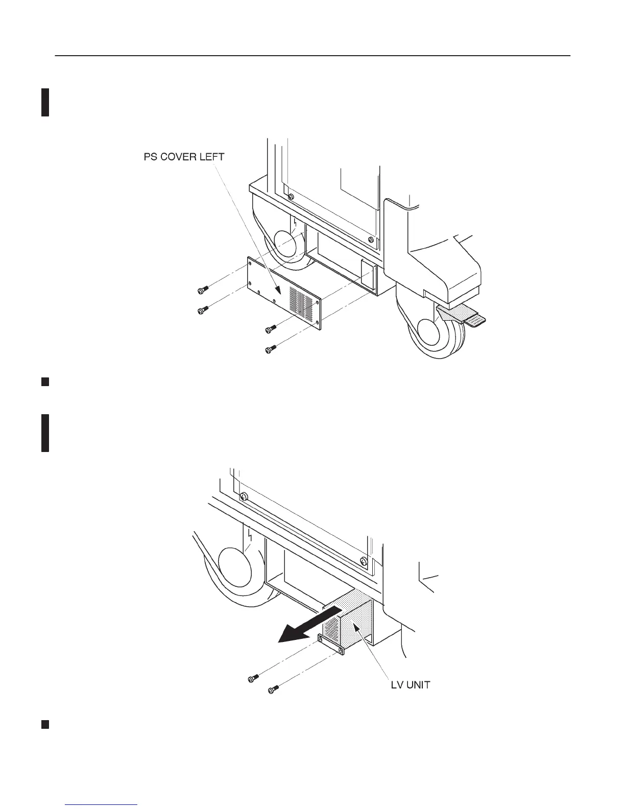
2. Unscrew four screws to remove the PS Cover Left. Refer to the ILLUSTRATION 4–29.
PS COVER LEFT REMOVAL
ILLUSTRATION 4–29
3. Unscrew two screws and pull the LV Unit out. Refer to the ILLUSTRATION 4–30.
Note
For the LV2 Unit and the LV3 Unit, the points for measuring and adjusting are located at the front of the
unit. It is not necessary to pull the LV unit out of the Power Supply Unit2 and Power Supply Unit3.
LV UNIT
ILLUSTRATION 4–30

 Loading...


