GE MEDICAL SYSTEMS
2127661
LOGIQ 400 SERVICE MANUAL
FUNCTIONAL CHECKS
4–4
REV 1
4–2 FUNCTIONAL CHECK PROCEDURES
4–2–1 Basic Controls
Step Check Expected result
1. Connect a sector or convex
transducer to ”Probe 2”
connector beneath keyboard.
2. Turn ON Power toggle switch.
3. Type USER ID and then press PATIENT ENTRY MENU should appear.
return key as necessary.
4. Press New Patient key. After a few seconds, the B mode screen should appear
as shown in ILLUSTRATION 4–1.
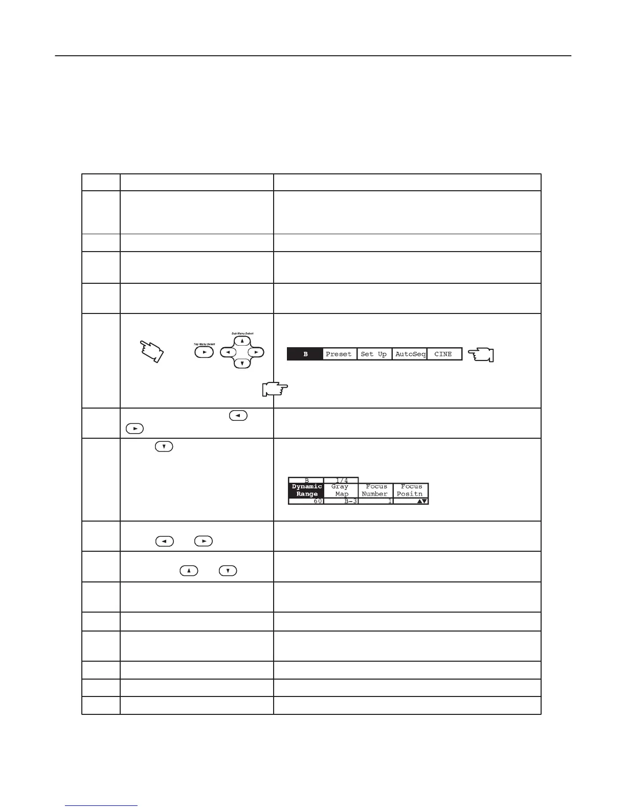
5. Press Top Menu Select key The top menu should appear on the CRT monitor screen
twice. as follows:
6. Select B section using or The B selection is displayed in reverse video.
key.
7. Press key. The B mode sub-menu should appear on CRT monitor
screen as follows:
8. Select Dynamic Range section The Dynamic Range selection is displayed in reverse
using or key. video.
9. Change Dynamic Range up/ Image grows softer and harder depending on position.
down using or key.
10. Press Top Menu Select key The menus on CRT monitor screen should disappear.
twice.
11. Rotate B/M Gain knob. Image grows lighter and darker with rotation.
12. Slide TGC potentiometers Image grows darker or brighter at depth equivalent to
(pots). pot’s location.
13. Rotate Depth knob. The depth of image should be magnified/reduced.
14. Press Reverse key. The image reverses the left/right orientation.
15. Press Reverse key again. The image reverses the left/right orientation.
Note
The items displayed on the Top Menu are different de-
pending on the component options.

 Loading...


