GE MEDICAL SYSTEMS
2127661
LOGIQ 400 SERVICE MANUAL
TM
8–86 OPTIONS
REV 5
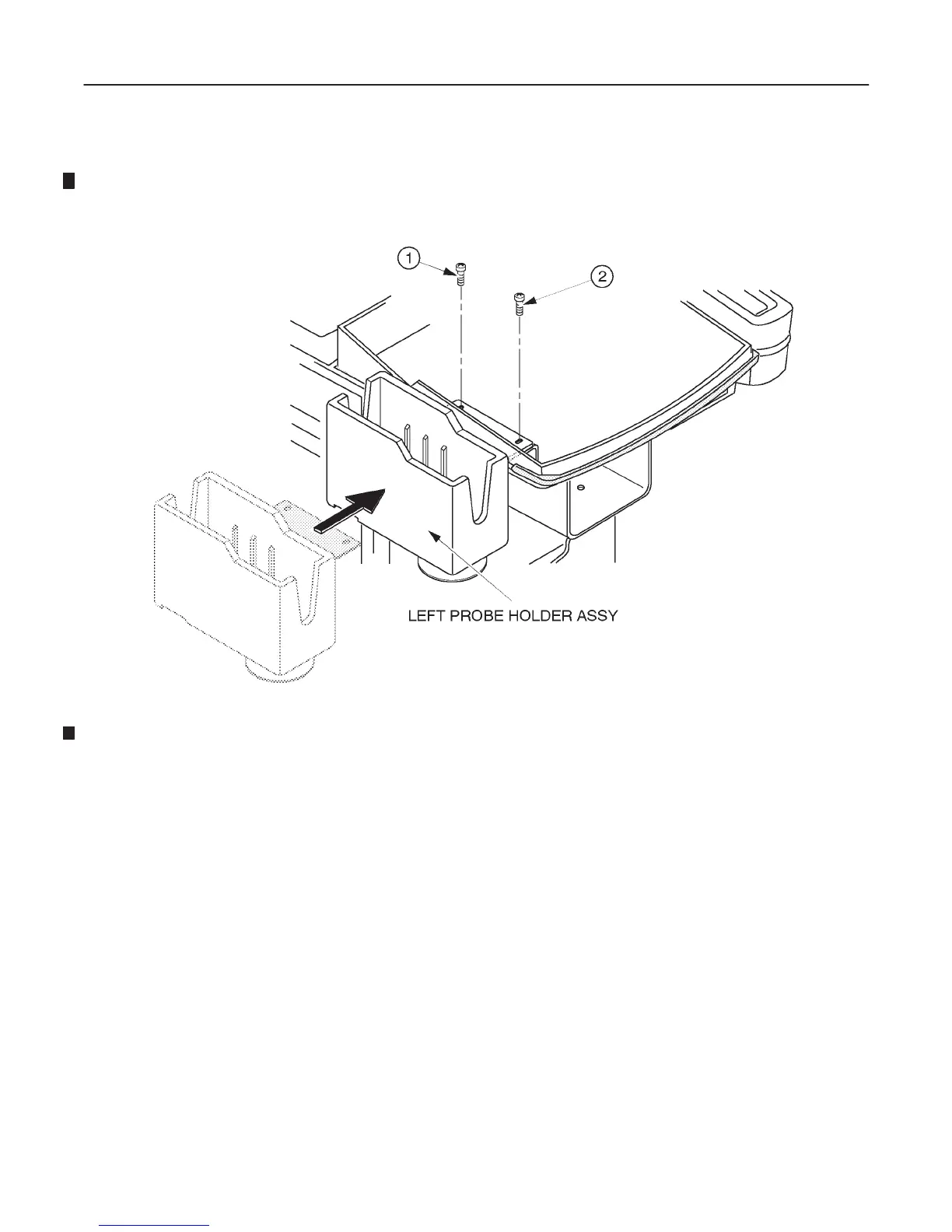
8–9–5 Installing Left Side Probe Holder (Continued)
4. Install the left side probe holder as shown in ILLUSTRATION 8–94.
LEFT SIDE PROBE HOLDER INSTALLATION
ILLUSTRATION 8–94
5. Re-assemble the keyboard panel assy.
8–9–6 Operational Check-out
1. Turn the system power ON.
2. Perform functional checks to verify that the keyboard panel assy is assembled correctly. Refer to Chapter 4,
FUNCTIONAL CHECKS.
3. Check that the left side probe holder is installed firmly.
8–9–7 Final Procedures
1. Properly dispose of excess material.
2. This completes the installation of the optional Left Side Probe Holder for LOGIQ 400.

 Loading...


