GE MEDICAL SYSTEMS LOGIQ 400 SERVICE MANUAL
2127661
5–18 DIAGRAMS
REV 9
5–8 CIRCUIT BOARD DESCRIPTION
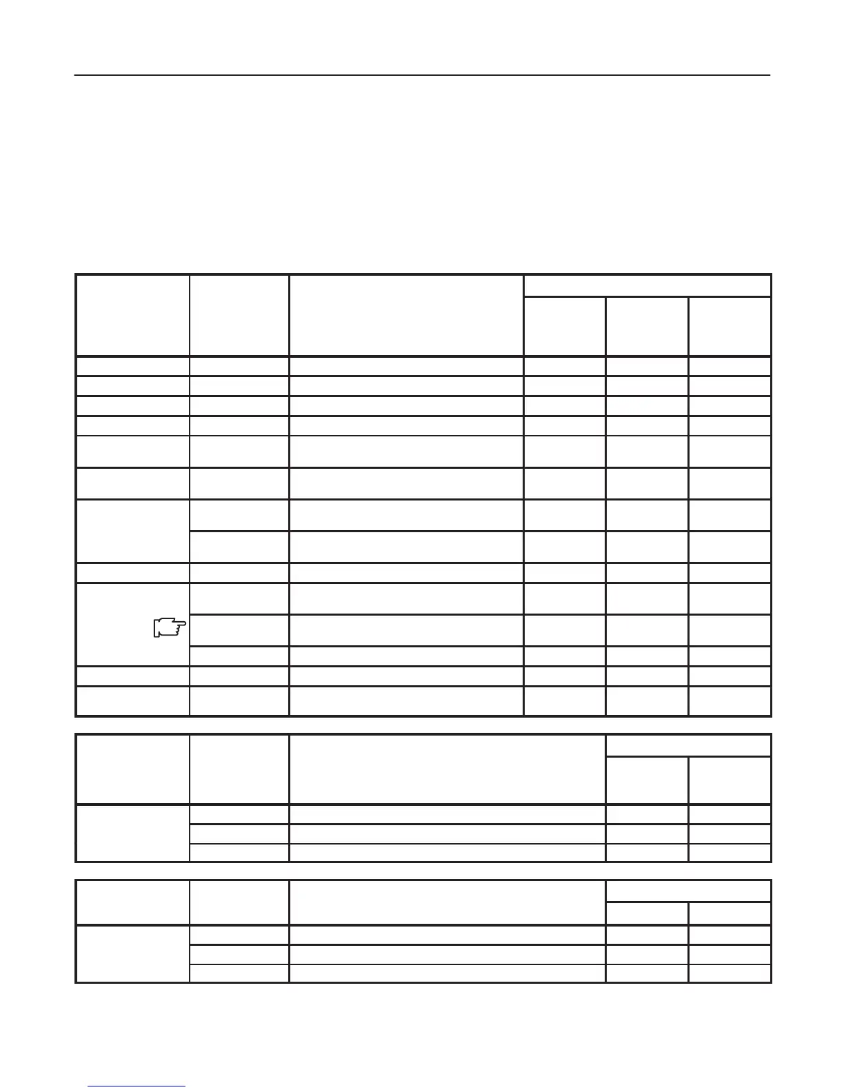
The following table lists circuit boards, their respective card cage slot assignments on the mother board and the loca-
tions of other circuit boards.
TABLE 5–1
CIRCUIT BOARD DESCRIPTION
CONSOLE TYPE
CARD CAGE SLOT NAME DESCRIPTIONS
COLOR
MONITOR
WITH VTR
PLAYBACK
COLOR
MONITOR
WITOUT VTR
PLAYBACK
BLACK &
WHITE
MONITOR
A1 TRDR ASSY Transmit Driver Assembly 1 1 1
A2 HBFR ASSY Hybrid Beam Former for Reception Assembly 1 1 1
A3 HBFR ASSY Hybrid Beam Former for Reception Assembly 1 1 1
A4 ASPR ASSY Analog Signal Processor Assembly 1 1 1
A7 BMRC ASSY B/M Mode Processor and Real Time Control-
ler Assembly
1 1 1
A8 DOPC ASSY Doppler and CFM Middle Processor Assem-
bly
1 1
A9 TLMC ASSY Time Line Memory Processor and Cine As-
sembly
1 1
TDCB ASSY Time Line Memory Processor, Cine, and Digi-
tal Scan Converter for B/W Assembly
1
A10 DSCC ASSY Digital Scan Converter CFM Assembly 1 1
A11 VIPB ASSY Video Output Processor with VTR Playback
Memory Assembly
1
VIPPASSY Video Assy with Interlace Progressive Scan
Coonverter and VCR Playback
1
VIDM ASSY Video Output Processor for B/W Assembly 1
A11 VIDM ASSY Video Output Processor for B/W Assembly 1
A12 MPU ASSY Master Controller and CPU Extend Board As-
sembly
1 1 1
CONSOLE TYPE
CARD CAGE SLOT NAME DESCRIPTIONS
COLOR
MONITOR
BLACK &
WHITE
MONITOR
REAR CONN
AVIF ASSY Audio and Video Interface Assembly 1
BVIF ASSY Video Interface Assembly for B/W Console 1
CNTIF ASSY Control Signal Interface Assembly 1 1
CONSOLE TYPE
2 SLOTS 3 SLOTS
PROBE CONN
PRAG ASSY Preamplifier Group Assembly 1 1
DCON ASSY Dual Connector Assembly 1
CONN1 ASSY Connector 1 Assembly 1

 Loading...


