EasyManuals Logo

GE LOGIQ 400 Service Manual

GE LOGIQ 400
526 pages
To Next Page IconTo Next Page
To Previous Page IconTo Previous Page
Page #245 background imageLoading...
Page #245 background image
GE MEDICAL SYSTEMS LOGIQ 400 SERVICE MANUAL
2127661
RENEWAL PARTS
6–115
REV 9
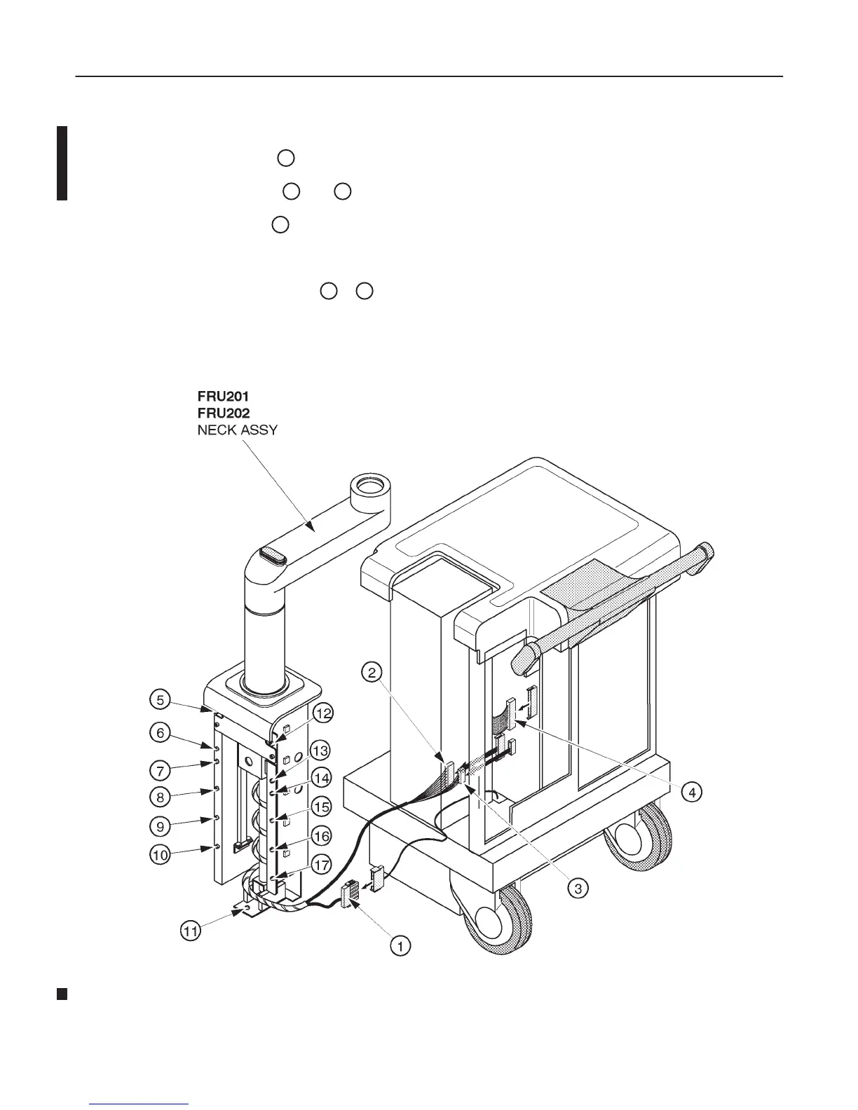
6–2–26 Neck Assy (FRU No. 201 for Color Monitor, No. 202 for B/W Monitor) (continued)
11. Disconnect one connector (
1
).
12. Disconnect two connectors (
2
and
3
) from the P25A and P26A connectors on Mother Board.
13. Disconnect one flat cable (
4
).
14. Cut off the tie wraps to bind cables.
15. Remove thirteen hexagonal bolts (
5
17
).
16. Remove the Neck Assy from console.
NECK ASSY DISASSEMBLY
ILLUSTRATION 6–47

Table of Contents

Other manuals for GE LOGIQ 400

Questions and Answers:

Question and Answer IconNeed help?

Do you have a question about the GE LOGIQ 400 and is the answer not in the manual?

GE LOGIQ 400 Specifications

General IconGeneral
BrandGE
ModelLOGIQ 400
CategoryMedical Equipment
LanguageEnglish

Related product manuals