GE MEDICAL SYSTEMS
2127661
LOGIQ 400 SERVICE MANUAL
7–18 PERIODIC MAINTENANCE
REV 5
7–3–5 ECG Leakage Current Test (Continued)
5. Set the meter’s “FUNCTION” switch to LEAD TO GROUND position to measure the patient lead to ground leak-
age current.
6. Select and test each ECG lead positions (except ALL) of the LEAD selector, testing each to the power condition
combinations shown in TABLE 7–6.
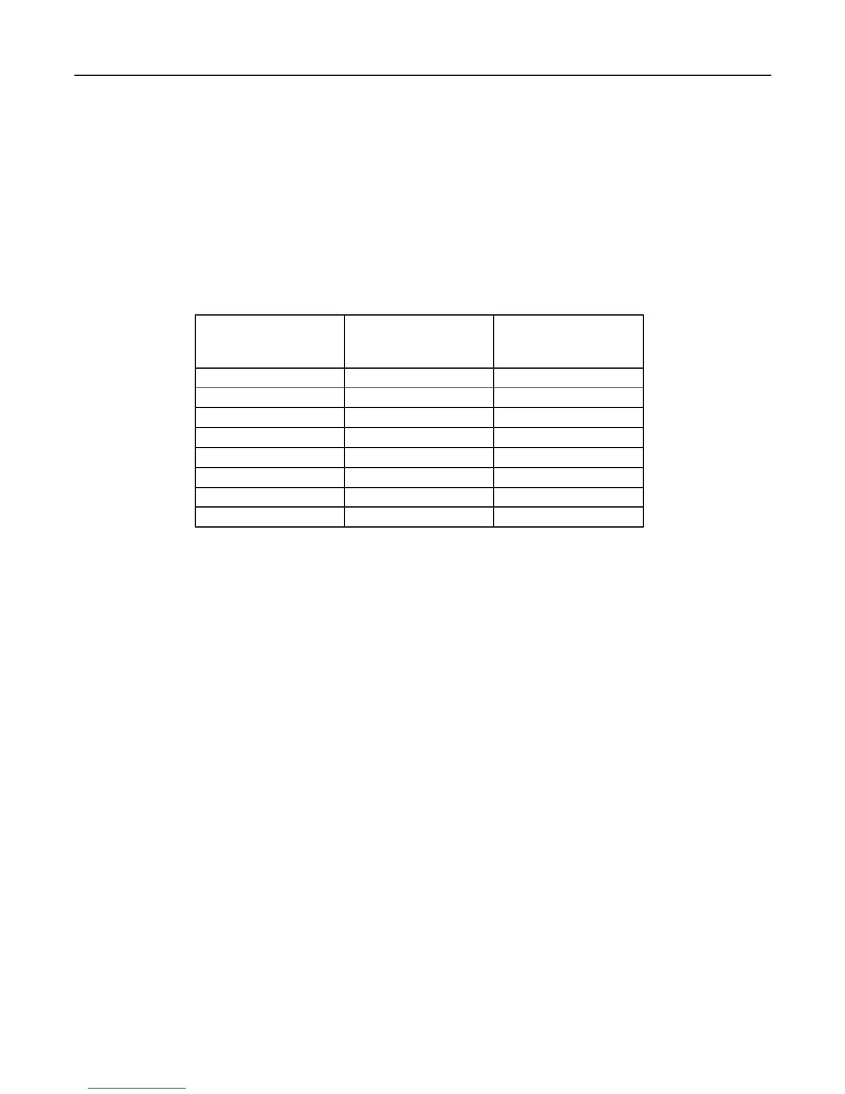
TABLE 7–6
TESTING POWER CONDITIONS
ECG Meter’s Meter’s
Power Polarity Neutral
Switch Switch
ON NORM CLOSED
ON NORM OPEN
ON REVERSE CLOSED
ON REVERSE OPEN
OFF NORM CLOSED
OFF NORM OPEN
OFF REVERSE CLOSED
OFF REVERSE OPEN
7. Record the patient lead to ground leakage current measured on the data sheet (Refer to TABLE 7–8).
8. Set the meter’s “FUNCTION” switch to LEAD TO LEAD position to measure the lead to lead leakage current.
9. Select and test each ECG lead positions (except ALL) of the LEAD selector, testing each to the power condition
combinations shown in TABLE 7–6.
10. Record the lead to lead leakage current measured on the data sheet (Refer to TABLE 7–8).
11. Set the meter’s “FUNCTION” switch to LEAD ISO position to measure the patient lead isolation current.
12. Select and test each ECG lead positions (except ALL) of the LEAD selector, testing each to the power condition
combinations shown in TABLE 7–6.
13. Depress the rocker switch to ISO TEST and read the isolation current. To apply the voltage to the lead safely, the
voltage is only applied when the rocker switch is depressed to ISO TEST.
14. Record the patient lead isolation current measured on the data sheet (Refer to TABLE 7–8).

 Loading...


