GE MEDICAL SYSTEMS
2127661
LOGIQ 400 SERVICE MANUAL
TM
8–61 OPTIONS
REV 5
8–5–8 Operational Check–out (Continued)
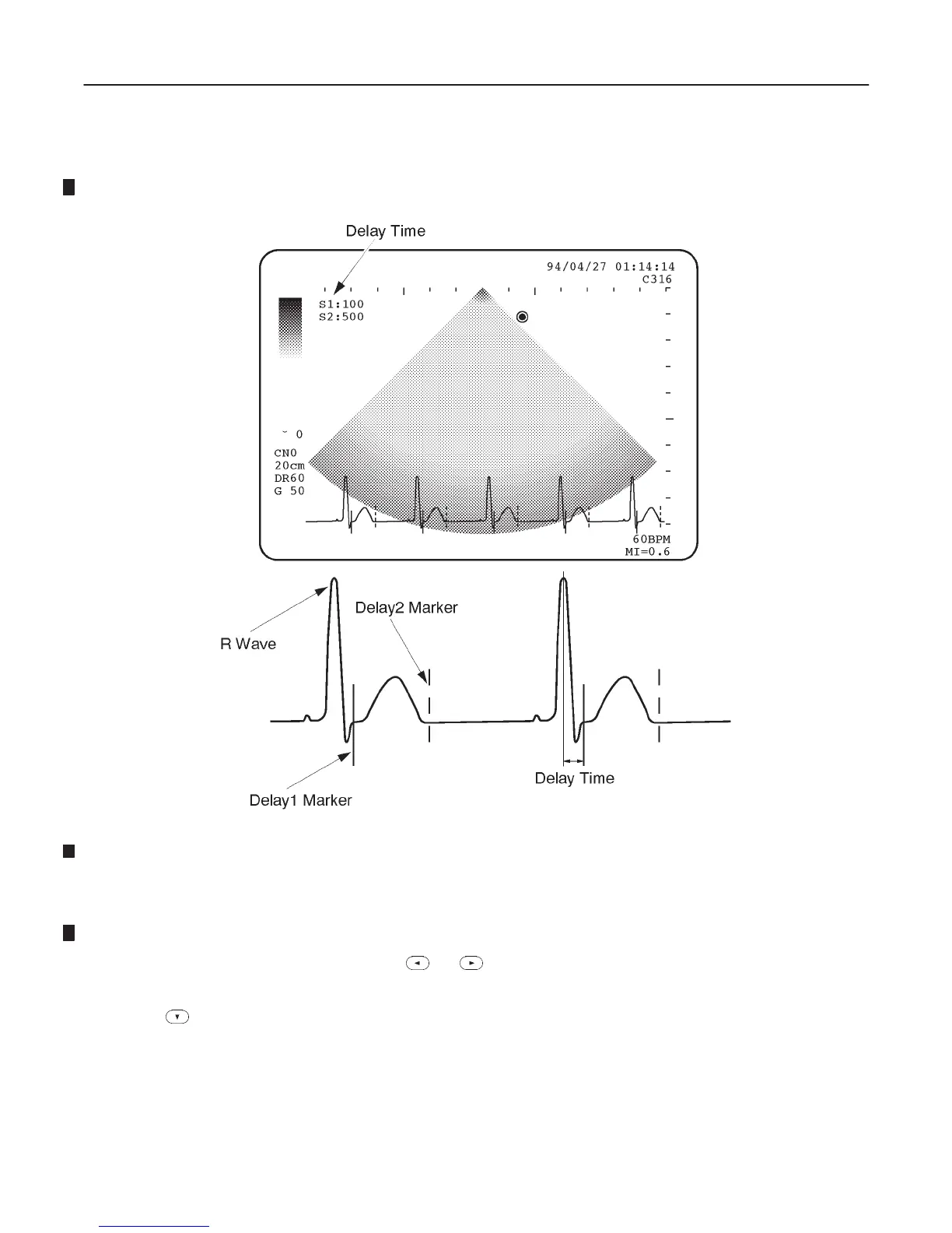
21. Check that the delay 1 markers (solid line) and delay 2 markers (broken line) appear on the CRT monitor screen
as shown in ILLUSTRATION 8–70.
ECG WAVEFORM (b)
ILLUSTRATION 8–70
22. Rotate the trackball when the R delay displayed on the CRT monitor screen is highlighted and set the delay time 1
(S1) to 100 msec. The delay time 1 (S1) and 2 (S2) are displayed at the upper left position on the CRT monitor
screen. Refer to ILLUSTRATION 8–70.
23. Select the Sync. Selectn section using the or key of Sub Menu Select keys. The Sync. Selectn section
is displayed in reverse video.
24. Press key to set the delay time 2 (S2).
25. Rotate the trackball and set the delay time 2 (S2) to 500 msec.
26. Check that the frozen images are displayed continuously in accordance with the timing when each delay marker
appears on the CRT monitor screen.

 Loading...


