106 GE INFORMATION D400 SUBSTATION GATEWAY INSTRUCTION MANUAL
CHAPTER 8: USING THE D400
System status LEDs
The System Status LEDs indicate the unit’s operational status:
The NET2 ACT/LINK LEDs on the front panel may not be properly driven on the D400 Main
Module with FPGA revision V1.4 and earlier when using the Redundant TP Ethernet + COM2
Port card (GE Item No. 520-0218LF). To check the FPGA revision, enter dmesg -s 16392 |
grep -i FPGA at the D400#>> command prompt and search for FPGA in the output.
Serial port status LEDs
The Serial Port Status LEDs provide a visual indication of the status for each serial
communication port. For a given serial communication port:
If a pair of LEDs is not lit, it does not indicate a problem, only that the connected device is
not active at that moment.
If a serial communication card slot is empty, (that is, no card is installed) the serial Receive
(RXD) LED may be lit.
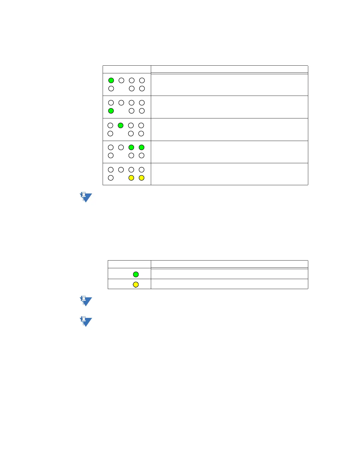
LED Display Status Description
Power is correctly supplied to the unit (+5 V present on the D400 Main
Board).
Initialization (boot-up and self-diagnostics) of the D400 is complete and the
unit is ready to process data.
IRIG-B signal is being correctly processed. This LED flashes at a 2 Hz rate.
Link integrity for the Ethernet Switch in NET1 and NET2 slots. See note below.
Transmission activity for the Ethernet Switch in NET1 and NET2 slots. See
note below.
LED Display Status Description
TXD Serial transmission activity on the serial port
RXD Serial reception activity on the serial port