180 GE INFORMATION D400 SUBSTATION GATEWAY INSTRUCTION MANUAL
APPENDIX B INSTALLING AND CONNECTING DNP3 I/O MODULES
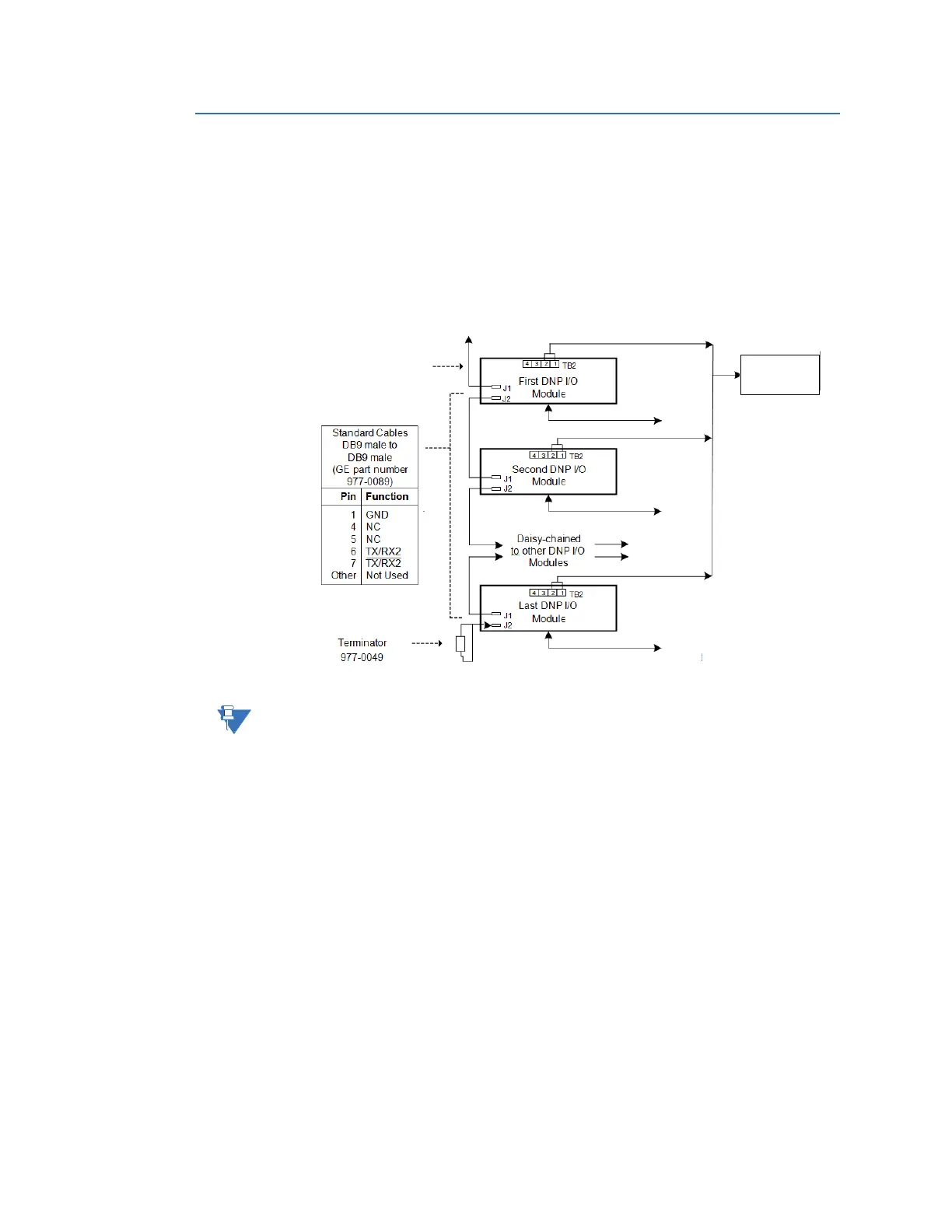
Connecting DNP3 I/O modules (High Voltage)
For a High-Voltage (HV) DNP I/O Module, for example: WESTERM D20SZ (517-0249-ML):
1. Interconnect the DNP3 link cabling between each DNP3 I/O module.
2. Connect pins 1 and 2 (and also pins 3 and 4 if a redundant power supply is used) on
TB2 to an External Power Supply (40 to 150 VDC) as shown in Figure 72.
Figure 72: Interconnect cabling between each DNP3 I/O module and power (HV)
The location of the External (Ext) Power Supply terminal varies between WESTERM I/O
module types.
Connecting to a D400
When connecting the DNP3 I/O modules to the D400, configure the D400 port for 2-wire
mode. Refer to section:
“RS-485 connections” on page 58 which indicates the
corresponding cable connections.
To D400 (RTU Master)
To Field Equipment
To Field Equipment
To Field Equipment
To Ext Power
To Ext Power
To Ext Power
To Ext Power
Cable: D400 (RTU Master)
GE Part Number: 977-0503
External DNP 3
I/O Module
Power Supply