CHAPTER 5: POWERING UP THE D400
D400 SUBSTATION GATEWAY INSTRUCTION MANUAL GE INFORMATION 85
3. Connect protective earth wire to the Protective Earth terminal on the rear panel.
The terminal is an M5 threaded stud with M5 nut and washers. The recommended
order for stacking the washers on the chassis is: flat washer, ground wire ring terminal,
toothed washer, M5 nut.
For proper transient protection, the recommended tool torque settings for the M5 nut
is 18.1 in-lb [2.04 Nm].
It is recommended to terminate 12 AWG green & yellow wire with a Panduit PV10-14R
or equivalent ring terminal.
4. Verify that Power LEDs on the front panel of the power supplies and the D400 main
module are lit.
5. Replace the terminal block protective plastic cover.
Power supply alarms
The D400 includes connections for two alarm outputs:
• Power Fail to indicate one of the two power supplies or one of the two power feeds
has failed
• System Fail to indicate system operation status
Terminal block TB2 on the rear panel of the D400 provides contact closure outputs for
connection to an external circuit, for example, to connect an external LED indicator or
audible alarm.
The contact closure used for alarm outputs is a solid-state photo-MOS device. Contact
closure output ratings at maximum ambient temperature are:
• Continuous current: 0.1 A continuous at 300 VAC / 300 VDC
• Peak current: 0.28 A peak for 10 ms
• Maximum on resistance: 35 ohm
• Dielectric isolation: 2 kV
RMS
Power fail alarm
The Power Fail contact closure provides for an external indication upon loss of power. The
Power Fail alarm is also indicated by the Power LED on the front panel of the power supply
turning off.
The front panel Power indicator LED is lit when any one power supply is ON, but does not
indicate that any one power supply has failed.
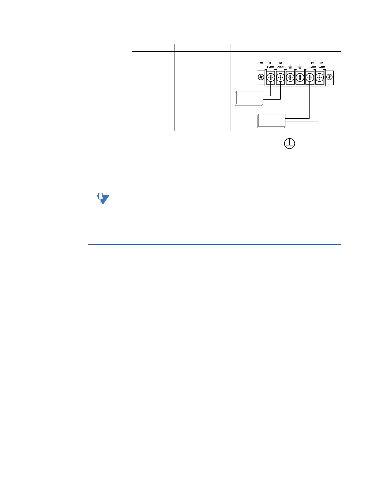
Two External DC
Power Sources
with Optional
Redundant D400
DC Power
Converter
First source connected
to
SUPPLY1 terminals.
Second source
connected to
SUPPLY2
terminals.
Power Source Connection Wiring Diagram
DC Power Source #1
DC Power Source #2
+
-
+
-
Supply 1
Supply 2