72 GE INFORMATION D400 SUBSTATION GATEWAY INSTRUCTION MANUAL
CHAPTER 4: CONNECTING TO DEVICES AND NETWORKS
2. The standby D400 unit attempts to pull the RS232 switch panel to assume the active
state.
3. The RS232 switch panel transfers all serial field connections to the standby D400,
which then becomes the active D400.
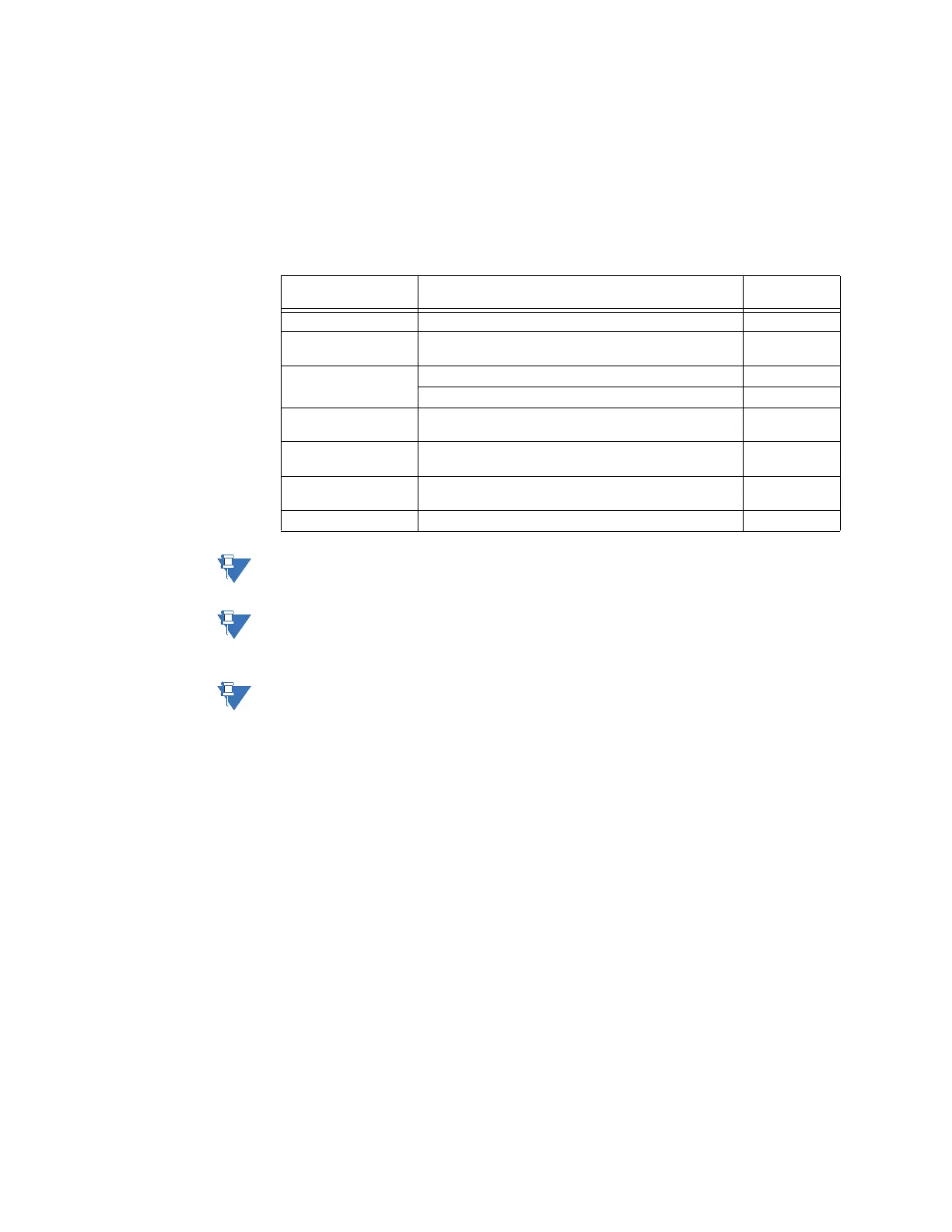
Required components
To implement a redundant D400 system, you need the following components:
:
The serial ports on your D400 are galvanically isolated from each other, however, when the
RS232 switch panel is used, the serial common of all ports are tied together.
Pins 4 on switch panel connectors J2 through J9 are tied together and to the panel’s power
supply. Any loading from field devices on these pins, loads the RS232 panel power supply
and should be taken into consideration when sizing power supplies.
The D400 RS232 adapter card that contains the redundancy control port must use the DTE
(default) switch positions. Refer to “Switch SW1/SW2 configuration” on page 38 and “Switch
SW3/SW4 configuration” on page 39. This card must also be revision 08A or higher (the
revision number is shown on a white label affixed to the top or bottom of the RS232
adapter card). If your card is 07C or below, please contact Technical Support.
To set up a redundant
system:
It is recommended that you install and configure one standalone D400 unit to ensure that
your configuration is valid and that device communications are operating properly. Once
this is done, proceed with the installation of the redundant system.
1. Mount the D400 units in a rack and connect power and ground. Refer to “Power
connections” on page 82.
2. Mount the RS232 switch panel.
3. Plug the connector of watchdog cable A (GE part number 977-0540) to a serial
connector on the first D400 (CCU A).
4. Plug the connector of watchdog cable B (GE part number 977-0541) to a serial
connector on the second D400 (CCU B). This cable must be connected to the same
serial port number on both units.
5. Connect the bare leads of both watchdog cables to TB1 on the RS232 switch panel
and the DB9 serial connector to either P1 or P9 as shown below.
6. Connect one end of the ping cable to the first D400 and the other end to the second
D400. This ping cable must be connected to the same serial port number on both
units.
Component Function GE part
number
RS232 Switch Panel Communications switch. 517-0247
Power Supply Power supply to power the RS232 switch panel.
Input: 85 – 264 VAC or 90 – 350 VDC.
580-0046
Watchdog Cable
Assembly
Connects D400 A to the RS232 switch panel. 977-0540
Connects D400 B to the RS232 switch panel. 977-0541
Ping Cable Assembly Links both D400 units to facilitate a heartbeat message
that determines the status of the active unit.
977-0146
RS232 Serial Cable Connects the D400 to the RS232 switch panel which is
then connected to external field devices.
977-0145
Power/SysFail Cable Connects the RS232 switch panel to an external power
supply and to the D400 SysFail terminal block.
970-0161
Ground Cable Provides a ground connection for the RS232 switch panel. 970-0182