160 GE INFORMATION D400 SUBSTATION GATEWAY INSTRUCTION MANUAL
CHAPTER 13: SERVICING THE D400
To remove and re-
insert the D400 main
module
1. Power down the D400.
2. Hand-loosen the two thumb screws on the front panel of the D400 main module.
3. Grasping the two handles, pull out the D400 main module.
4. Make the necessary changes.
5. Slide the main module back into the chassis. Push firmly to ensure the connectors at
the rear of the main board are fully seated.
6. While pressing the main module panel against the chassis frame, hand-tighten the
two thumb screws (applying a torque of no more than 5.8 in-lb [0.66 Nm]) on the front
panel.
7. Power up the D400 and verify that the Power LED is illuminated.
Replacing the battery
The lithium battery maintains power to the D400's NVRAM if there is a power disconnect.
The D400 is supplied with a 1/2AA 3.6 V 0.9 Ah Lithium battery that you must insert on the
D400 main board when the D400 is installed. To ensure the battery is good, it is
recommended you check the battery voltage before installation and replace the battery
every five years.
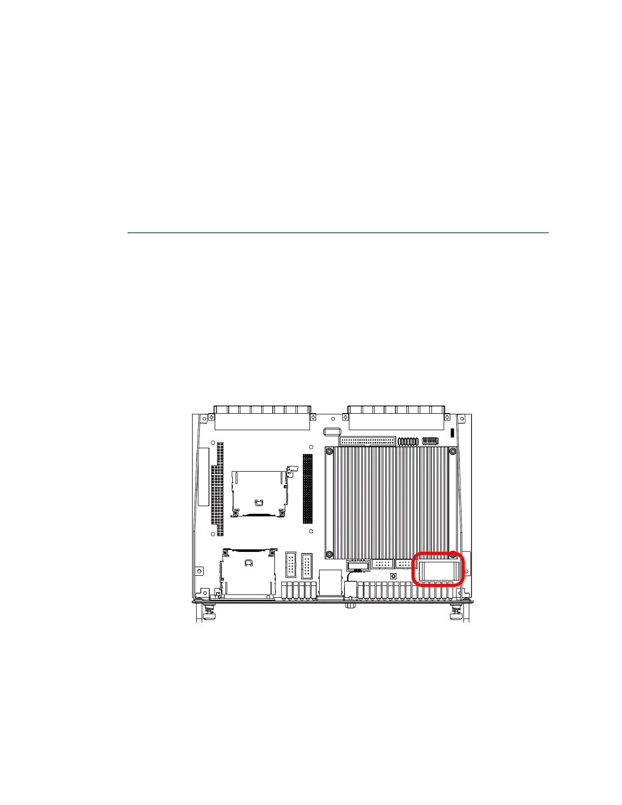
You can access the battery compartment by removing the D400 main module from the
chassis. The battery holder BT1 is located near the front corner of the board, behind the
two rows of Serial Port Status LEDs.
Figure 63: D400 Battery Location