CHAPTER 3: SETTING UP COMMUNICATION CARDS
D400 SUBSTATION GATEWAY INSTRUCTION MANUAL GE INFORMATION 37
See “RS-232 connections” on page 58 for typical cable connections and connector pin
outs.
Configuration options
The RS-232 card supports the following configuration options on each port:
• DCE (Data Communications Equipment), if SW1/SW2 pin 1 is set to A
• DTE (Data Terminal Equipment), if SW1/SW2 pin 1 is set to A
• +5V (320mA) output on pin 1 of rear DB9 connector if. SW1/SW2 position 1 is OFF and
position 2 is set to ON.
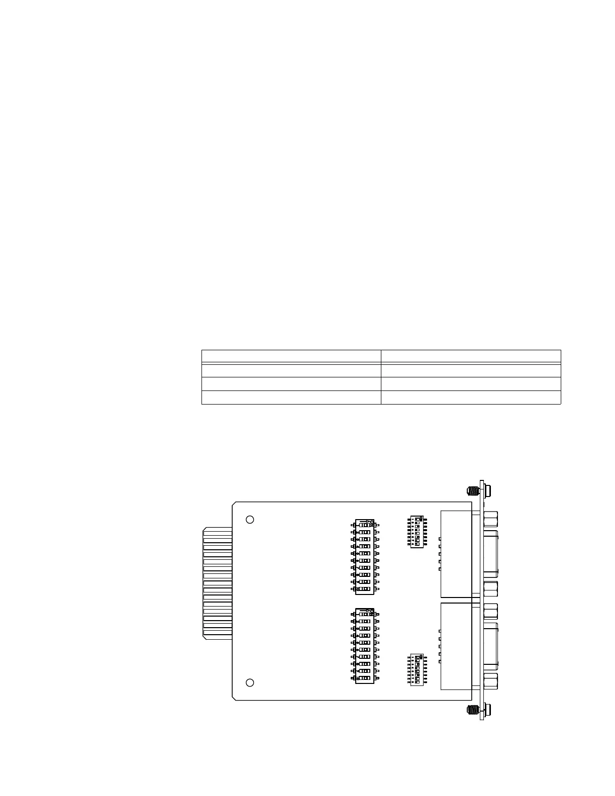
Refer to module layout drawing 520-0207-ML for details.
In addition, the RS-232 card is configurable to optionally provide an IRIG-B signal (on pin 4)
and individually isolated Ground (on pin 6).
The signal type and pin options for each port are selectable via two sets of switches on the
RS-232 card:
•Port 2 (J2) is configured by switches SW1 and SW3
•Port 1 (J3) is configured by switches SW2 and SW4
Follow instructions for setting the switches to select the appropriate functions for each
port.
The signal format outputted to the RS-232 cards is dependent upon the format applied to
the IRIG-B input adapter:
Factory default
The factory default setting is DTE on each port.
Figure 9: RS-232 adapter top side
IRIG-B Input Format... IRIG-B Output Format...
Pulse Width Modulated (B0xx) Pulse Width Modulated (B0xx)
Manchester (B2xx) Manchester (B2xx)
AM Modulated (B1xx) Pulse Width Modulated (B0xx)