60 GE INFORMATION D400 SUBSTATION GATEWAY INSTRUCTION MANUAL
CHAPTER 4: CONNECTING TO DEVICES AND NETWORKS
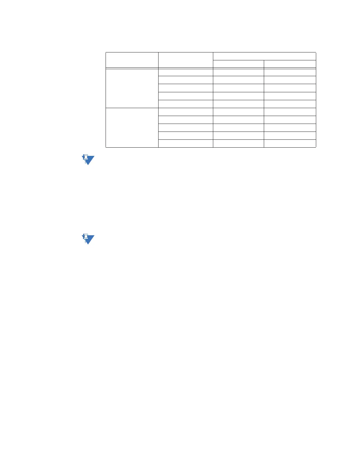
Table 14: RS-485 2-Wire Terminal Block Signal Definitions
The terminal block positions are numbered from 1 to 10 starting from the bottom of the
card.
4-Wire connections
See “RS-485 adapter” on page 40 for configuration options.
To connect RS-485 4-
wire type devices to
the RS-485 Adapter
Use the following wiring connection:
Before wiring devices, ensure that the RS-485 Adapter is configured to 4-wire mode (see
“RS-485 adapter” on page 40).
RS-485 Channel Position Number 2-Wire
Function Signal Flow
Channel 1 1 TX1+ IN/OUT
2 TX1− IN/OUT
3 FGND 1 Shield
4 RX1− -
5 RX1+ -
Channel 2 6 TX2+ IN/OUT
7 TX2− IN/OUT
8 FGND 2 Shield
9 RX2− -
10 RX2+ -