178 GE INFORMATION D400 SUBSTATION GATEWAY INSTRUCTION MANUAL
APPENDIX B INSTALLING AND CONNECTING DNP3 I/O MODULES
Connecting DNP3 I/O modules (Low Voltage)
For a Low Voltage (LV) DNP3 I/O module, connect the:
• Interconnect cabling between each DNP3 I/O module, and
• Power to the last DNP3 I/O module of the chain.
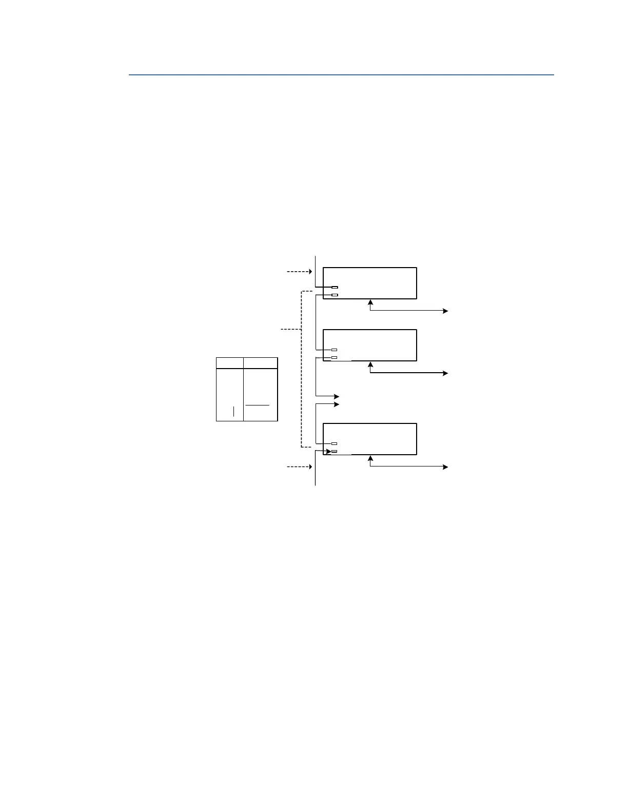
DNP3 I/O module (LV) interconnect cabling
The DNP3 I/O module interconnect cabling is shown in Figure 70.
Figure 70: Interconnect cabling between each DNP3 I/O module and power (LV)
After DNP3 I/O modules have been interconnected, you are now ready to connect power
to the DNP3 I/O modules. See
“DNP3 I/O module (LV) connection to the Power Source” on
page 179.
First DNP I/O
Module
Second DNP I/O
Module
J1
To Field Equipment
To Field Equipment
J1
J2
J2
Daisy-
chained
to other DNP I/O
Modules
Module
To Field Equipmen
Pin
1
4
5
6
7
Othe
Function
DC1
Not Used
To RTU Maste
To Power Source
Standard Cables
0089)
RTU Maste
Cable
GE Part
Numbe
Serve
0503
Cable: GE Part Numbe
J1
J2
DB9 male
(GE part numbe
Cable: D400 (RTU Master)
GE Part Number: 977-0503
To D400 (RTU Master)
To Field Equipment
To Field Equipment
To Field Equipment
To Power Source
J1
J2
J1
J2
J1
J2