APPENDIX B: INSTALLING AND CONNECTING DNP3 I/O MODULES
D400 SUBSTATION GATEWAY INSTRUCTION MANUAL GE INFORMATION 177
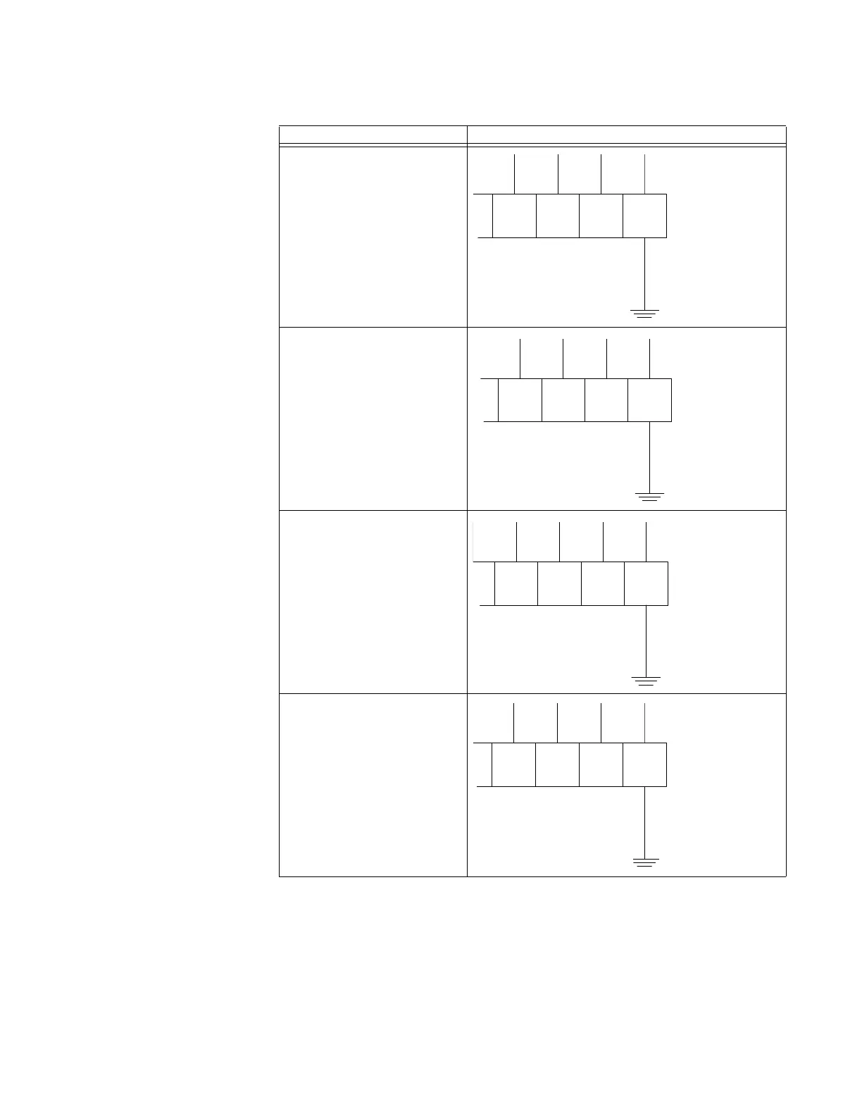
Table 57: Site ground connection examples
After site ground has been connected, you are now ready to connect power, and DNP3 link
cabling to the DNP I/O module. See
“Connecting DNP3 I/O modules (Low Voltage)” on
page 178 or “Connecting DNP3 I/O modules (High Voltage)” on page 180.
Module Type Site Ground Connection
DC Analog Input Module
Digital Input Module
Control Output Module
Combination Input Output Module
12 AWG
GND Wire
Site
100
47
97
48 49 50
98 99
TB1
2.05 mm (12 AWG)
green wire
Site Ground
12 AWG
GRN GND
Site
132
63
129
64 65 66
130 131
TB1
2.05 mm (12 AWG)
green wire
Site Ground
12 AWG
GRN GND
Site
106
50
103
51 52 53
104 105
TB1
2.05 mm (12 AWG)
green wire
Site Ground
Site
100
47
97
48 49 50
98 99
TB1
12 AWG
Green Wire
2.05 mm (12 AWG)
green wire
Site Ground