CHAPTER 5: POWERING UP THE D400
D400 SUBSTATION GATEWAY INSTRUCTION MANUAL GE INFORMATION 87
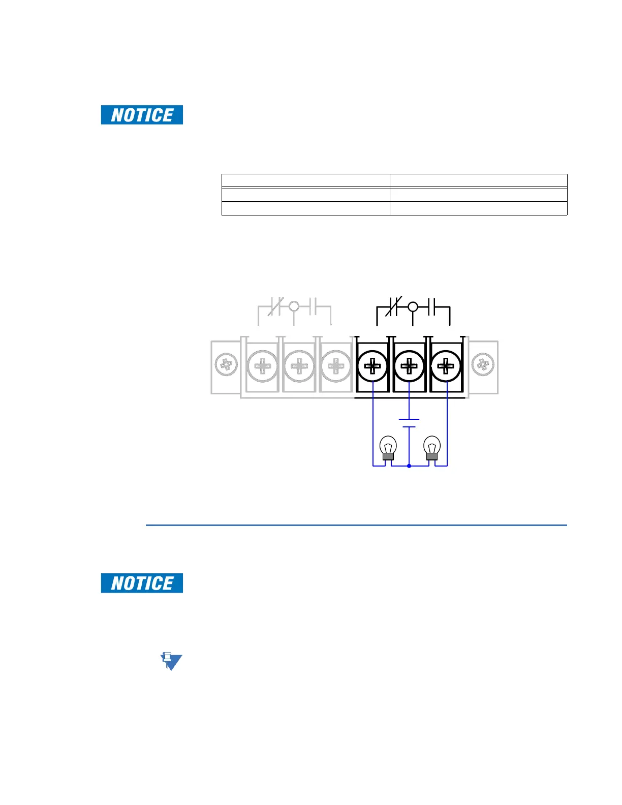
The System Fail contact closure provides three contacts (terminals 4, 5 and 6) on terminal
block TB2.
Contact closure rated for 0.1 A @ 300 V maximum.
To connect the
System Fail relay
1. Remove the terminal block protective plastic cover.
2. Wire a lamp to terminals 4, 5 and 6 on terminal block TB2 as follows:
For proper connection, the recommended tool torque settings for power terminal
screws are 10.8 in-lb [1.22 Nm].
3. Replace the terminal block protective plastic cover.
Figure 51: System Fail Alarm Connection
Powering down the D400
Powering down or shutting down the D400 without using the proper procedure could
result in loss of system log data (SOE log, alarm log, user log, etc.), and could prevent the
D400 from restarting properly. Follow the instructions provided to shut down the D400
safely.
The D400 is like a computer and the system must be shut down properly before removing
the power. For the shut down procedure, see
“Shutting down the D400” on page 112.
It may take a couple of minutes for the D400 to fully shut down and for the CPU Ready LED
to go off.
Once you have completely shut down the D400, you can safely disconnect the power.
To enable the indicator when system is… Wire the lamp between…
Failed Terminals 4 and 5
Functioning properly Terminals 5 and 6
Light ON
after failure
Light ON
when operational
Station Battery / Power Source
Power
Fail
System
Fail
TB2