CHAPTER 4: CONNECTING TO DEVICES AND NETWORKS
D400 SUBSTATION GATEWAY INSTRUCTION MANUAL GE INFORMATION 59
RS-485 channels on a single terminal block: Channel 1 on terminals TB1-1 through TB1-5
and Channel 2 on terminals TB1-6 through TB1-10. Terminal blocks accept a range of 24-
14 AWG [0.2-2.1
mm²] Recommended wire strip length is 0.2" [5.0 mm]. Screws shall be
torqued with tool setting of 4.2 in-lb [0.46 Nm]. A 3.0 to 3.5 mm flat screwdriver tip is
recommended.
The transceiver in 2-wire mode and the receiver in 4-wire mode present 1 unit load (UL),
nominally 12 KOhm, to the external network with switches SW3/SW4 all off.
See “RS-485 adapter” on page 40 for configuration options.
Cabling requirements
The recommended total maximum length for RS-485 cables is 4000 ft [1300 m] when
operating at 115 kbps. Refer to the manual of the connecting device for its recommended
maximum cable length.
The cables must be shielded and the shield of each RS-485 cable section should be
grounded at one end only. This prevents circulating currents and can reduce surge-
induced current on long communication lines.
The RS-485 Adapter supports a maximum of 32 transceivers of standard unit load per
channel (64 unit loads per RS-485 Adapter card).
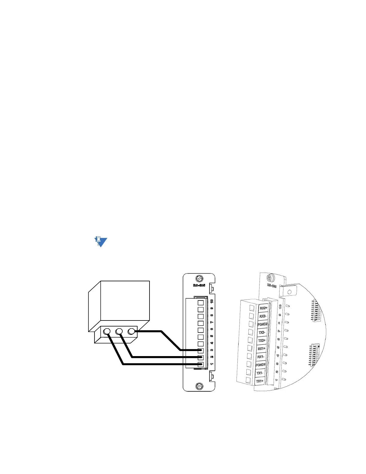
2-Wire connections
To connect RS-485 2-
wire type devices to
the RS-485 Adapter
Use the following wiring connection:
Before wiring devices, ensure that the RS-485 Adapter is configured to 2-wire mode (see
“RS-485 adapter” on page 40).
Figure 32: RS-485 2-wire devices - wiring connection