64 GE INFORMATION D400 SUBSTATION GATEWAY INSTRUCTION MANUAL
CHAPTER 4: CONNECTING TO DEVICES AND NETWORKS
LED transmitters are classified as IEC 60825-1 Accessible Emission Limit (AEL) Class
1M. Class 1M devices are considered eye safe to the unaided eye. Do not view directly
with optical instruments.
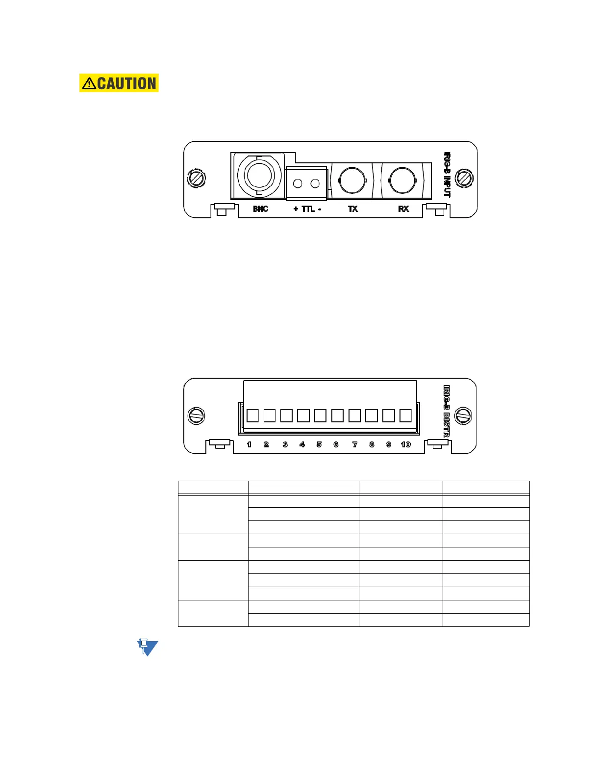
Figure 36: IRIG-B Input Adapter
IRIG-B distribution adapter
The IRIG-B Distribution Adapter (GE Item No. 520-0212LF) is an optional IRIG-B output card
to supply a pulse width coded IRIG-B (TTL) signal passed from the IRIG-B Input card to
attached IEDs. The IRIG-B Distribution card provides four channels on a single terminal
block. Each channel is capable of supplying a signal to up to four IEDs, for a total of 16
IEDs. The IRIG-B Distribution card plugs into a dedicated IRIG-B slot (slot 10) on the D400.
Terminal blocks accept a range of 24 to 14 AWG [0.2 to 2.1 mm²] Recommended wire strip
length is 0.2" [5.0 mm]. Screws shall be torqued with tool setting of 4.2 in-lb [0.46 Nm]. A 3.0
to 3.5 mm flat screwdriver tip is recommended.
Figure 37: IRIG-B Distribution Adapter
Table 16: IRIG-B Distribution Terminal Block Signal Definitions
The terminal block positions are numbered from 1 to 10 starting from the bottom of the
card.
Channel Terminal Block Position Function Signal Flow
Channel 1 1 IRIG-B TTL OUT
2 GND -
3 FGND -
Channel 2 4 IRIG-B TTL OUT
5 GND -
Channel 3 6 IRIG-B TTL OUT
7 GND -
8 FGND -
Channel 4 9 IRIG-B TTL OUT
10 GND -