CHAPTER 4: CONNECTING TO DEVICES AND NETWORKS
D400 SUBSTATION GATEWAY INSTRUCTION MANUAL GE INFORMATION 67
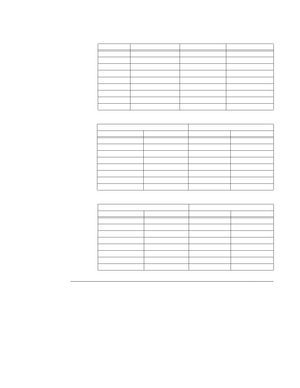
Table 18: Ethernet RJ-45 Connector Signal Definitions
Table 19: Ethernet Crossover Cable (RJ-45) Pin Out
Table 20: Ethernet Straight-Through Cable (RJ-45) Pin Out
Modem connections
A COM2 port is provided on the COM2 Port Adapter or the Redundant TP Ethernet + COM2
Port Adapter. The COM2 port can support serial connections for the following dial-up
interfaces:
• External modem
• Point-to-point protocol (PPP) services
•Wide area network
Position Function Signal Flow Color
1 RX+ IN White w/ Orange
2 RX− IN Orange
3 TX+ OUT White w/ Green
4 P1+ - Blue
5 P1− - White w/ Blue
6 TX− OUT Green
7 P2+ - White w/ Brown
8 P2− - Brown
Shield - -
D400 Switch/Hub
Name Pin Pin Name
TX_D1+ 1 3 RX_D2+
TX_D1− 2 6 RX_D2−
RX_D2+ 3 1 TX_D1+
RX_D2− 4 2 TX_D1−
BI_D3+ 5 7 BI_D4+
BI_D3− 6 8 BI_D4−
BI_D4+ 7 4 BI_D3+
BI_D4− 8 5 BI_D3−
D400 PC
Name Pin Pin Name
TX_D1+ 1 1 RX_D2+
TX_D1− 2 2 RX_D2−
RX_D2+ 3 3 TX_D1+
RX_D2− 4 4 TX_D1−
BI_D3+ 5 5 BI_D4+
BI_D3− 6 6 BI_D4−
BI_D4+ 7 7 BI_D3+
BI_D4− 8 8 BI_D3−