68 GE INFORMATION D400 SUBSTATION GATEWAY INSTRUCTION MANUAL
CHAPTER 4: CONNECTING TO DEVICES AND NETWORKS
The COM2 port provides a single DB-9 connector wired for an RS-574 DTE signal. The COM2
Port Adapter plugs into any NET slot (slots 11 and 12) of the D400. The Redundant TP
Ethernet + COM2 Port Adapter plugs into the NET1 slot (slot 11).
The COM2 Port requires an external modem to provide dial-up functionality.
See “COM2 port adapter” on page 51 for more information.
To connect a modem
to the COM2 Port
Adapter
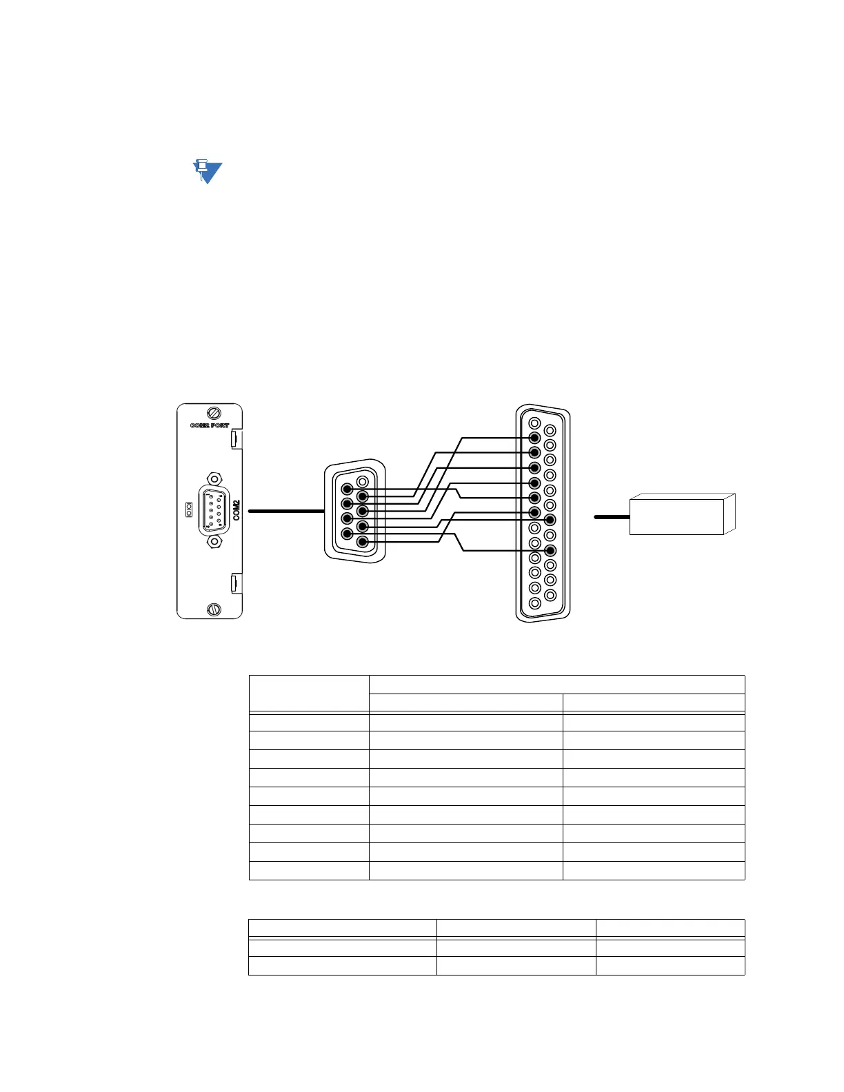
Connect a straight-through modem cable (not supplied with the D400) to the modem and
the D400 COM2 port. Connect using the settings provided below.
Modem Settings:
• Baud rate: 38400 bps
• Data bits: 8
• Parity: Disabled
• Stop bit: 1
Figure 40: Modem to COM2 port 2 adapter
Table 21: COM2 Port DB-9 Connector Signal Definitions
Table 22: COM2 Port DB-9 to DB-25 Pin Out
1
13
14
25
1
5
6
9
2
3
20
7
22
4
5
6
Modem
Pin Number DTE
Signal Acronym Signal Flow
1 DCD IN from DCE
2 RXD IN from DCE
3 TXD OUT to DCE
4 DTR OUT to DCE
5 Signal GND -
6 DSR IN from DCE
7 RTS OUT to DCE
8 CTS IN from DCE
9 Not connected -
Signal Acronym DB-9 Pin # DB-25 Pin #
TD 2 3
RD 3 2