CHAPTER 4: CONNECTING TO DEVICES AND NETWORKS
D400 SUBSTATION GATEWAY INSTRUCTION MANUAL GE INFORMATION 61
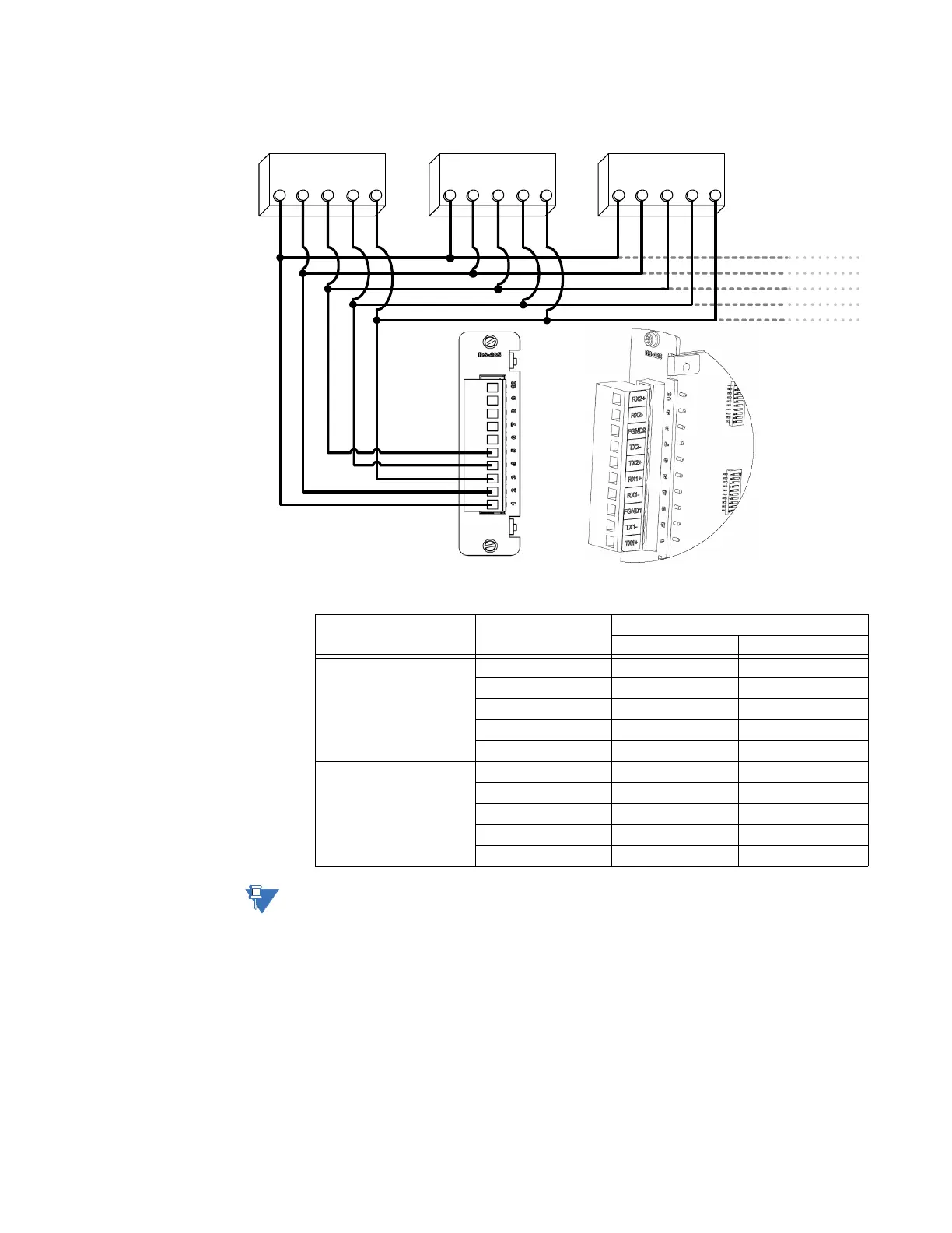
Figure 33: RS-485 4-wire devices - wiring connection
Table 15: RS-485 4-Wire Terminal Block Signal Definitions
The terminal block positions are numbered from 1 to 10 starting from the bottom of the
card.
Device 1
RX+ RX- TX+ TX- GND
Device 2
RX+ RX- TX+ TX- GND
Device 3
RX+ RX- TX+ TX- GND
RX1+
RX1-
FGND1
TX1-
TX1+
RS-485 Channel Position Number 4-Wire (default)
Function Signal Flow
Channel 1 1 TX1+ OUT
2 TX1− OUT
3 FGND 1 Shield
4 RX1− IN
5 RX1+ IN
Channel 2 6 TX2+ OUT
7 TX2− OUT
8 FGND 2 Shield
9 RX2− IN
10 RX2+ IN