x/EN ST/Na7
-
MiCOM P74
Menu Text Default Setting
Setting Range
Step Size
Min. Max.
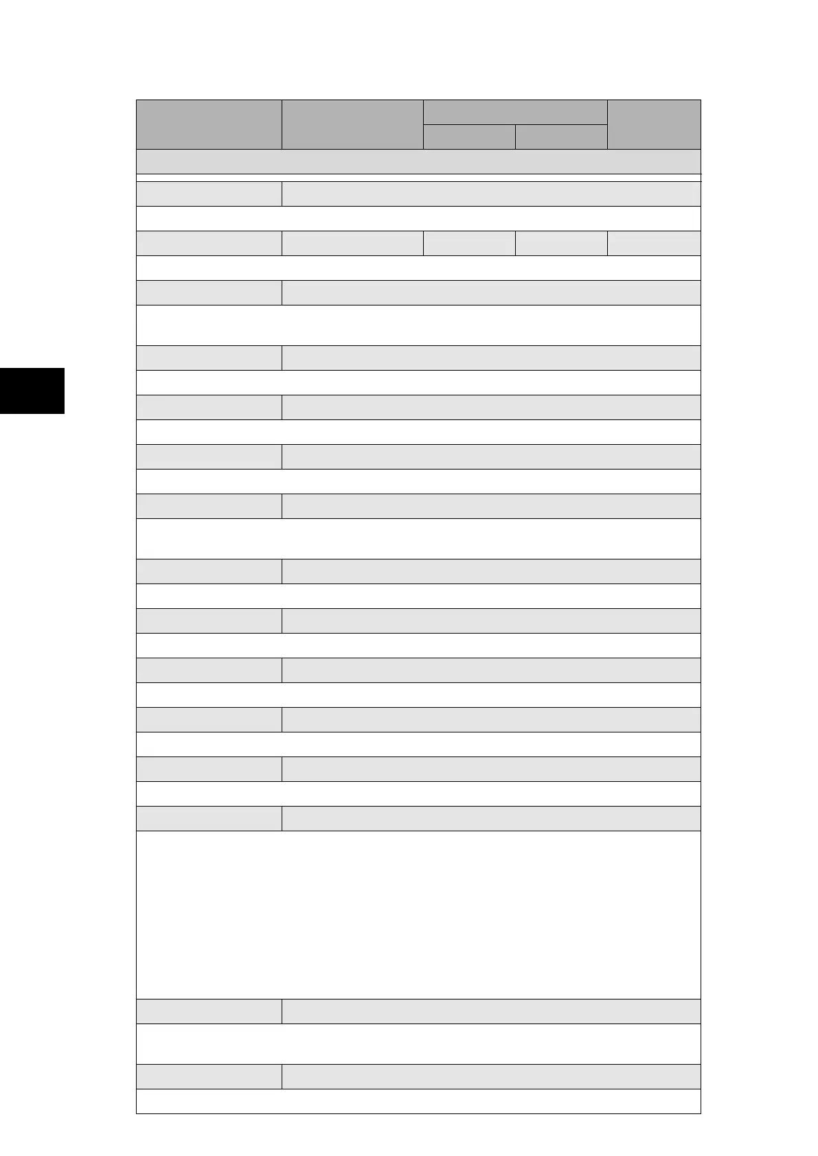
SYSTEM DATA
Comms. Level 2
Displays the conformance of the relay to the Courier Level 2 comms.
Relay Address 255 6 6 1
Fixed front and first rear port relay address.
Plant Status 0000000000000000
Displays the circuit breaker plant status for up to 8 circuit breakers. The P741 relay does
not support any circuit breaker. Not used
Control Status 0000000000000000
Not used.
Active Group 1
Displays the active settings group.
Software Ref. 1
Displays the relay software version including protocol and relay model.
Software Ref. 2
Software Ref. 2 is displayed for a relay with IEC 61850 protocol only and displays the
software version of the Ethernet card.
Opto I/P Status 00000000
Duplicate. Displays the status of opto inputs.
Relay O/P Status 00000000
Duplicate. Displays the status of output relays.
Alarm Status 1 00000000000000000000000000000000
32 bits field give status of first 32 alarms (refer to P74x/EN MR for alarm list).
Alarm Status 2 00000000000000000000000000000000
Next 32 alarm status defined.
Alarm Status 3 00000000000000000000000000000000
Next 32 alarm status defined. Assigned specifically for platform alarms.
Access Level 2
Displays the current access level.
Level 0 - No password required - Read access to all settings, alarms, event records
and fault records
Level 1 - Password 1 or 2 required - As level 0 plus: Control commands, e.g. circuit
breaker open/close
Reset of fault and alarm conditions, Reset LEDs
Clearing of event and fault records
Level 2 - Password 2 required - As level 1 plus: All other settings
Password Control 2
Sets the menu access level for the relay. This setting can only be changed when level 2
access is enabled.
Password Level 1 ****
Allows user to change password level 1.