8-76 Section 8-5 - Electronic Boards- Replacement Procedures
D
IRECTION 5771498-100, REVISION 6 VENUE™ SERVICE MANUAL
PRELIMINARY
7.) Loosen the 2 screws that secure the T-TRx Box and remove the T-TRx box.
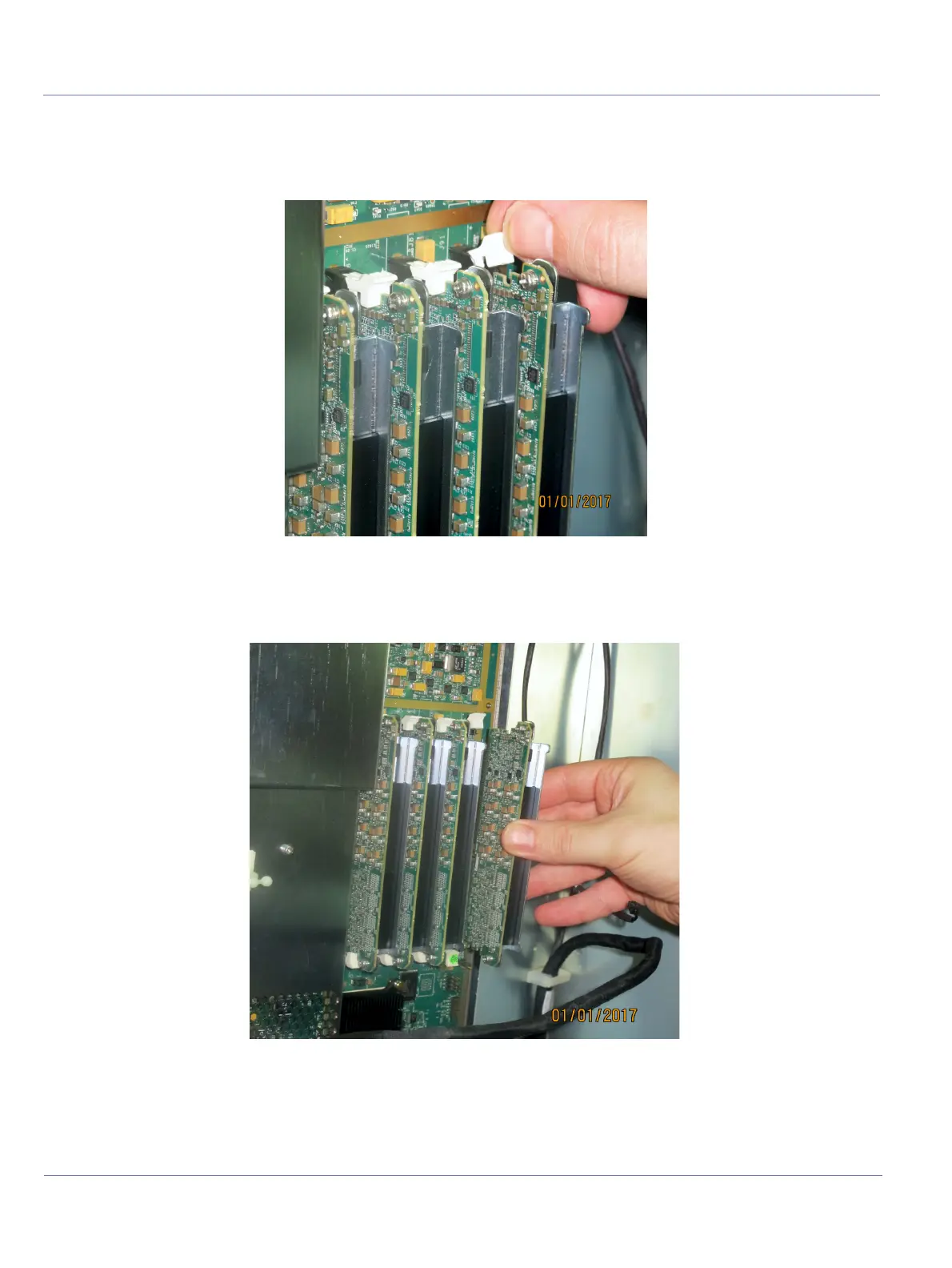
The four T-TRx modules are each secured in position on the T-CFE Board by way of a white plastic
holder at each end of the T-TRx module. These are opened by gently pulling them outwards to tilt
the holder away from the edge of the module, as shown in Figure 8-60.
8.) Open each white plastic holder located on either end of the first TRx Module to release the module
then slide the module towards you to remove it.
9.) Repeat Steps 4 - 6 to remove each of the remaining TRx Modules.
Figure 8-60 TRx Module Secured with Plastic Holders
Figure 8-61 Removing a TRx Module

 Loading...


