8-126 Section 8-6 - Mechanical Parts- Replacement Procedures
D
IRECTION 5771498-100, REVISION 6 VENUE™ SERVICE MANUAL
PRELIMINARY
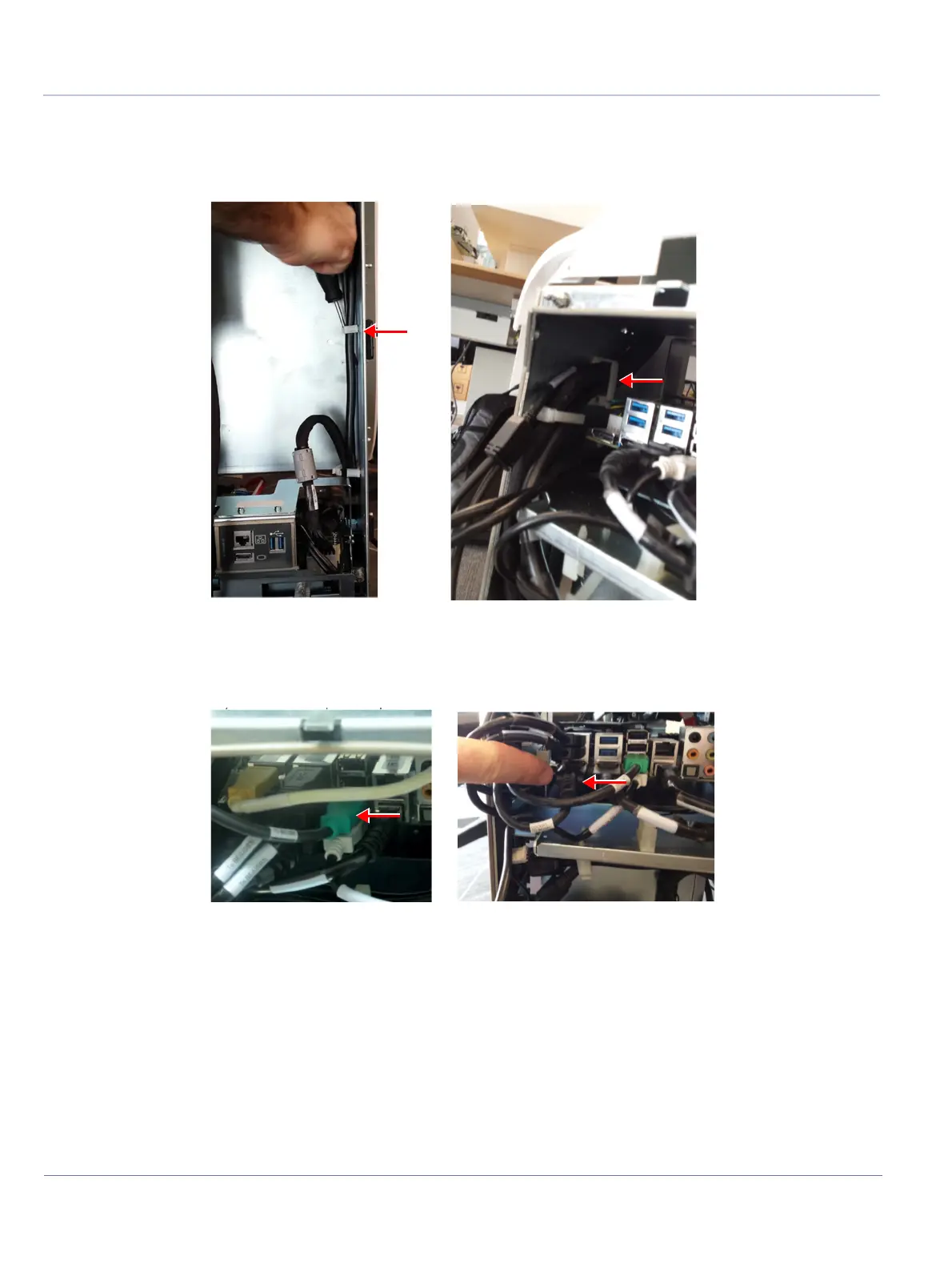
8.) Release the plastic clips that hold the cable using a flat screwdriver:
• Three in the front end
• One between the connectors and the MPB receptacle side.
9.) Disconnect the Cockpit to BEP split cable connected to BE module (green USB connector and black
display port connector).
10.)Open cable cover door:
a.) Open the captive screw of the cable cover door using a Phillips screwdriver.
b.) Slide the cable cover door towards you, to free the cable
c.) Slide the cable connectors upwards and gently route them- one after the other - through the
Figure 8-122 Plastic Clips Holding the Cable
Figure 8-123 Disconnecting Cables Connected to BE Module

 Loading...


