8-128 Section 8-6 - Mechanical Parts- Replacement Procedures
D
IRECTION 5771498-100, REVISION 6 VENUE™ SERVICE MANUAL
PRELIMINARY
8-7-3-5 BE to Cockpit Cable Installation Procedure
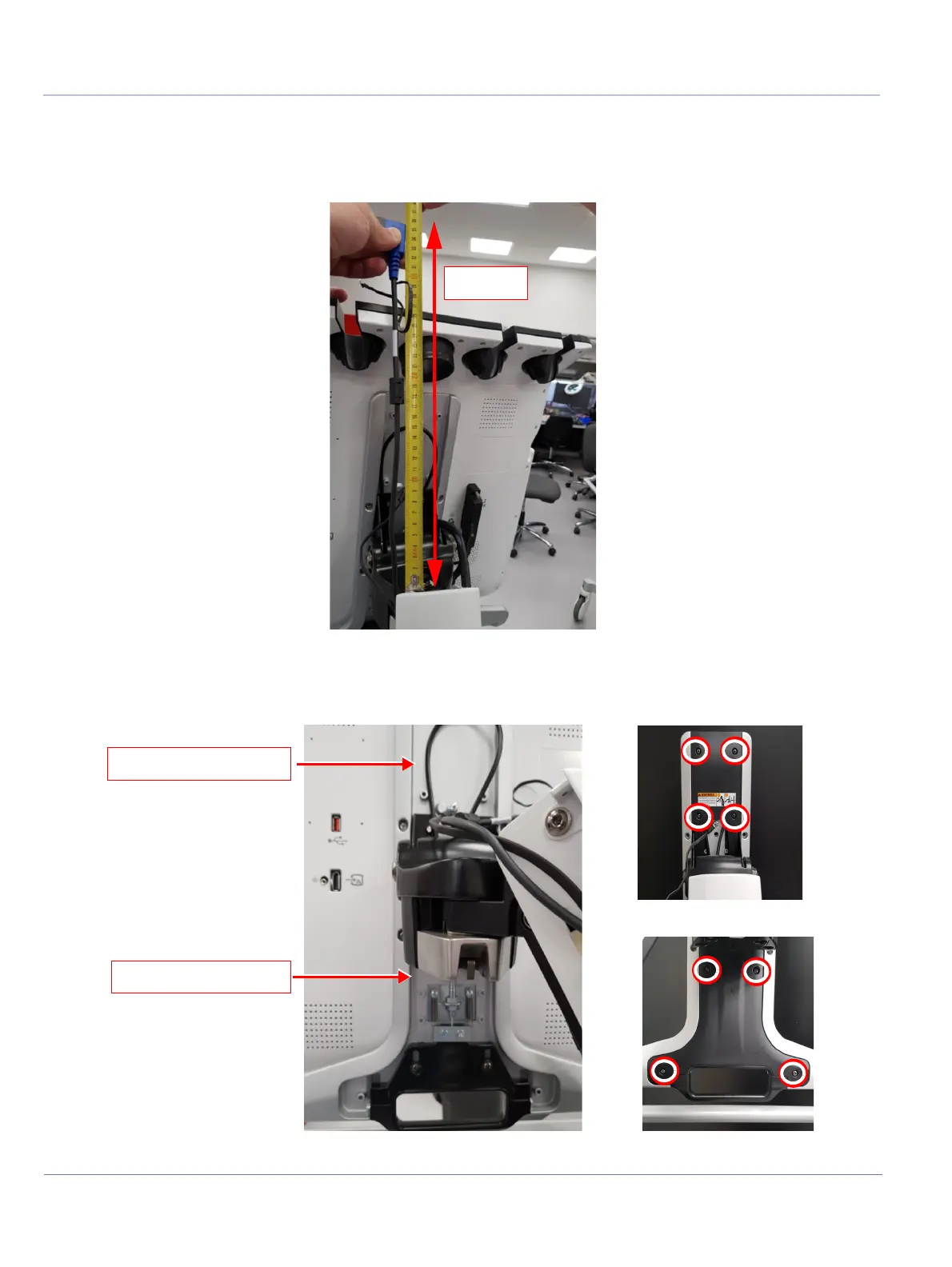
1.) Route BE to Cockpit Cable through arm, so that the cable length that remains exposed to the
cockpit direction is minimum 35cm.
2.) Remove the lower and then the upper cockpit covers.
Figure 8-125 Routing BE to Cockpit Cable - Measuring 35 cm
Figure 8-126 Removing Upper and Lower Cockpit Covers
Upper cover removed
Lower cover removed

 Loading...


