8-130 Section 8-6 - Mechanical Parts- Replacement Procedures
D
IRECTION 5771498-100, REVISION 6 VENUE™ SERVICE MANUAL
PRELIMINARY
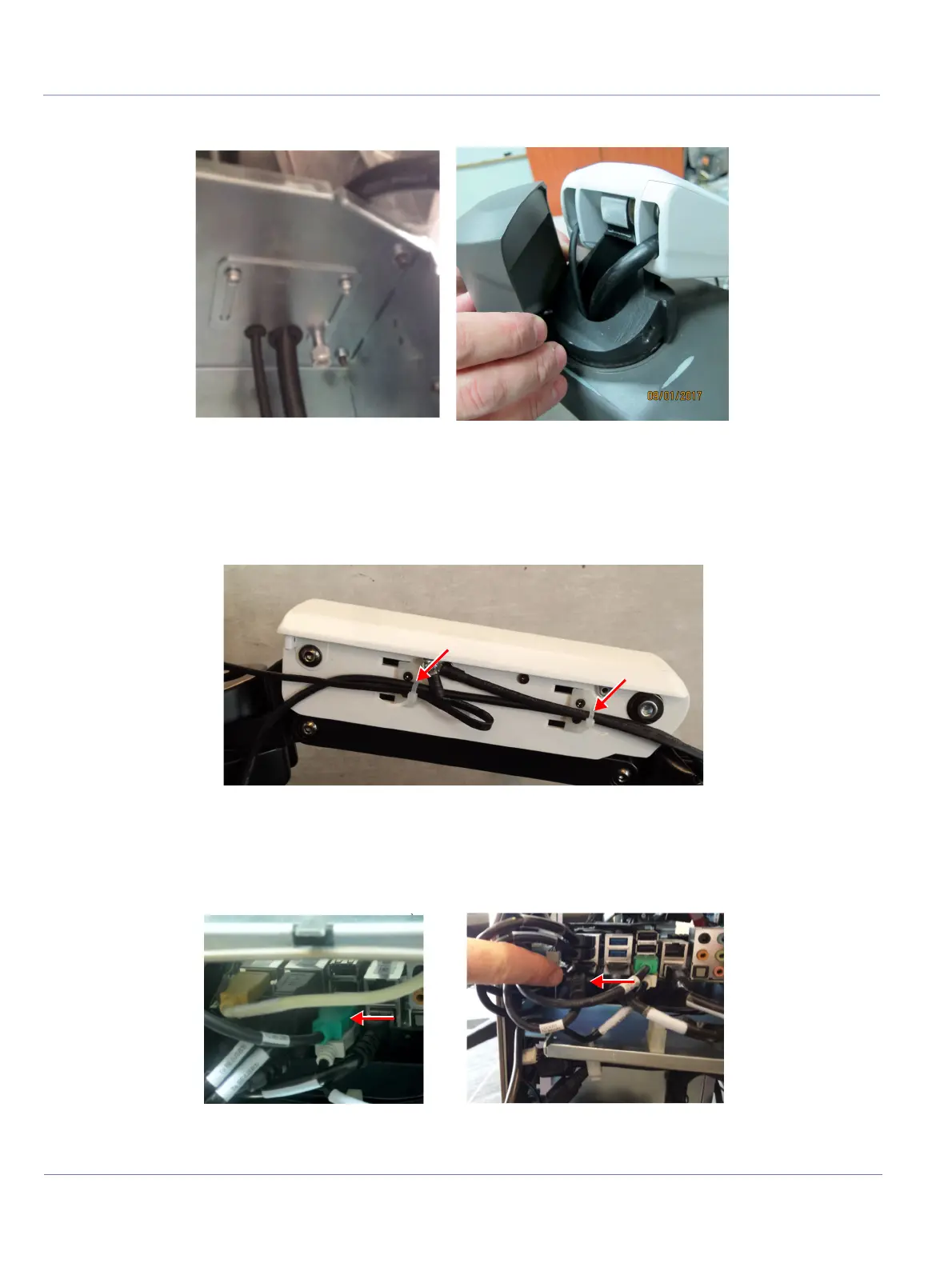
7.) Route the BE TO COCKPIT cable through the cable cover door and the arm hole.
8.) Connect the BE TO COCKPIT CABLE to the monitor
• Connect the cable connector (use flat-head screwdriver)
• Connect Ground cable (use Phillips screwdriver).
9.) Gently slide the BE TO COCKPIT cable through the MPB receptacle side, towards the front.
10.)Reconnect the Cockpit to BEP split cable connected to BE module (green and black). Ensure the
cables are connected to the correct locations (see cable diagram below).
11.)Secure the cable to the plastic clips.
Figure 8-129 Route Cable Through Arm Hole
Figure 8-130 Securing Cable to Arm
Figure 8-131 Reconnecting the BR Module Cables

 Loading...


