Battery Charger
Control Unit Parts
Control unit and power unit are placed in charger transport case.
iCharger 3010B is installed as control unit.
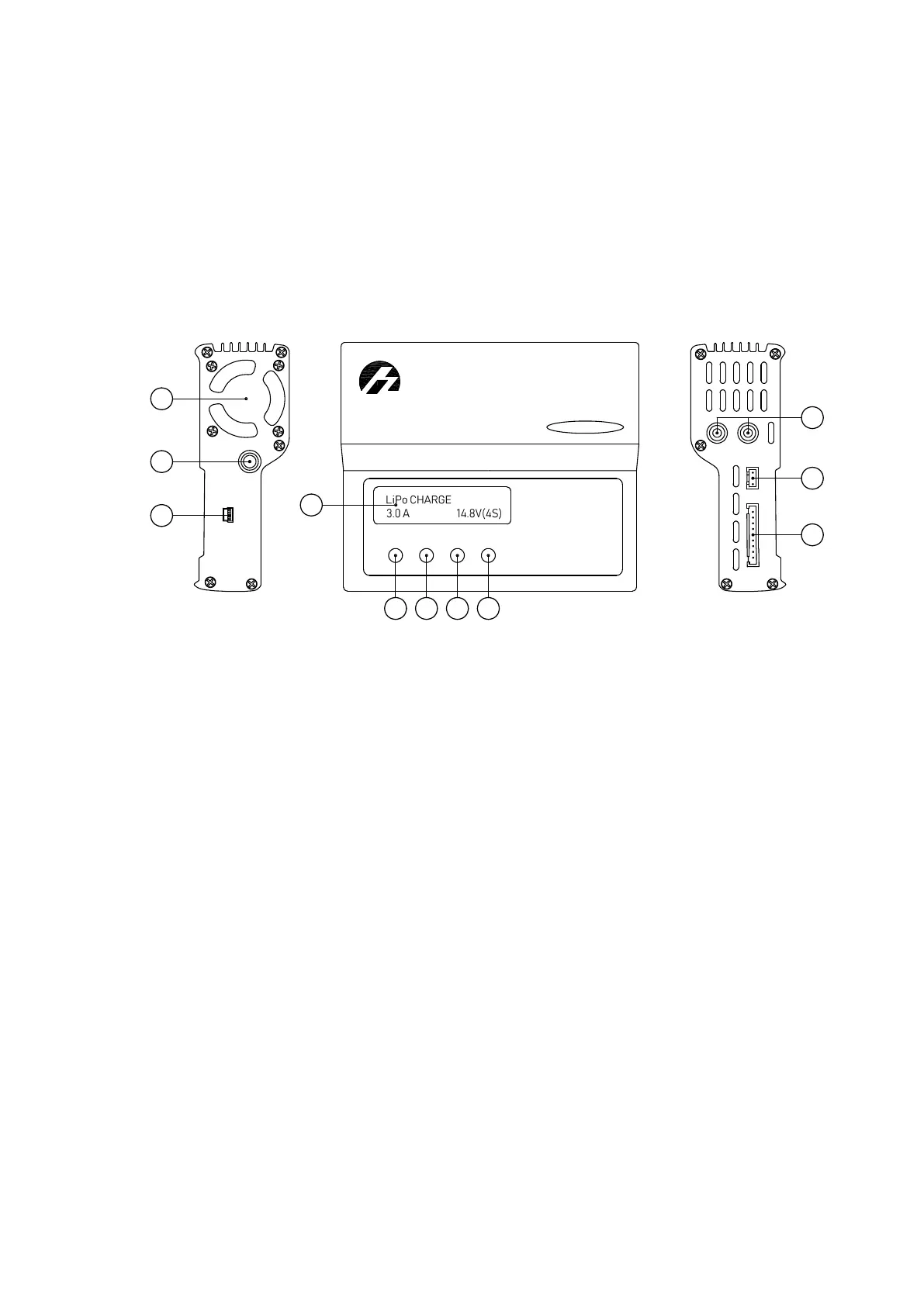
The picture below shows main parts of this device.
Ba
lan
ce
Po
rt
+ O
U
TP
UT -
Te
mp
.
iCharger
Sy
nc
h
rono
us
B
alan
ce
C
harg
e
r/D
isch
a
rg
er
3010B
USB
1
2
3
4
9
10
11
5 6
7
8
1. Cooling Fan 6. Dec — «Left» Button
2. DC Cable 7. Inc — «Right» Button
3. Port miniUSB
8. Start/Enter — Approve Settings and
Start Charging Button
4. LCD Screen 9. Output Ports
5. Batt type/Stop — Battery Type and Stop
button
10. Temperature Sensor Port
11. Balance Socket
66