Handheld Tester Emulator Test Suite
2
PAGE 71
The HHT continuously monitors and displays voltage levels while the Power Supply Voltage Test screen is
displayed. The HHT continuously:
• takes a No Load voltage measurement
• switches in the Load resistor
• allows the voltage to stabilize
• takes a Full Load voltage measurement
• switches out the Load resistor
• allows the voltage to stabilize
The current test status is displayed in the upper right corner of the screen. The test status is ‘Untested’ the
first time through the test suite. If a test suite is continued, this status will be either ‘Passed’ or ‘Failed’
depending on the selected results file.
Press the Next button to continue on to Test C - Standard Load Cycle Test. The HHT logs the measured
voltages, along with the Pass / Fail test results, then advances to the next test.
This is the first test displayed when the Emulator Test Suite option is selected. The Start option is
removed, and the ‘Left’ and ‘Right’ arrow buttons have no affect. Use the ‘Next’ button to advance to
the next test in the Test Suite.
Handheld Tester Emulator Test Suite
2
PAGE 72
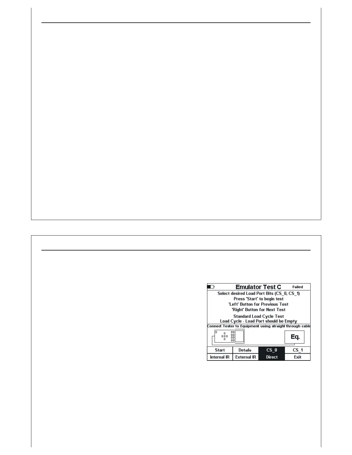
Figure 61 - Test C Setup Screen
Active Mode Functionality Test C
Verify Single handoff sequence for Loading.
Verify single handoff sequence for Loading. See Figure 2 for example signal timing diagram.
Test C is implemented using the Active Mode Load Cycle
screen. This screen runs a standard Load Cycle test using
CS_0 (default) or CS_1. The operator should select the
desired port selection signal. Typically, CS_0 should be used.
Figure 61 shows the test setup screen for Test C. The
connection method defaults to Direct. The operator should
select the desired connection method. The test title is
displayed in the middle of the screen.
When the Start option is selected, the Active Mode Load
Cycle screen is displayed.
Figure 61 shows an example of a Failed test status. When
‘Failed’ is displayed at the upper right of the screen, the current test results indicate that this test had
failed the last time it ran.