Do you have a question about the Get Control E84 and is the answer not in the manual?
Describes the DB-25 socket housing, its locks, and its function for external transceiver connection.
Details the DB-25 pin housing, its locks, and its interface for direct connection to load ports.
Explains the DB-9 socket housing configuration for Data Terminal Equipment (DTE) and its interface.
Explains the keypad layout and soft key operation for menu navigation and selection.
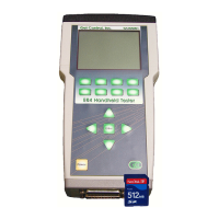
Details the SD card slot, insertion, and removal procedure for data storage.
Specifies compatibility with FAT16 file system and warnings about formatting.
Describes how test results files are organized by Tool ID in folders on the SD Card.
Explains the structure and content of Tool ID files for organizing test results.
Details the naming convention (XXNNNNNN.DAT) for stored test result files.
Outlines the 9-line format required for creating Tool ID text files.
Describes the process of saving test results, including the Save Test Results screen.
Explains how to create and edit Tool ID records using the Edit Tool Details screen.
Details the test to verify load port power supply voltage and its requirements.
Explains how to view voltage and current levels for E84 signals in Active or Passive mode.
Describes the screen displaying the IR Loopback Test progress and verification.
Presents the statistical results of the IR Transceiver Test, including pass/fail status.
Provides specific details about errors detected during the IR Transceiver Test.
Shows voltage and current measurements taken during the IR Transceiver Test for ON/OFF states.
Displays E84 inputs and outputs in a real-time graph for manual control operations.
Allows viewing real-time data from the DLD via a graph window.
Explains storing and uploading DLD log files using the PSS.
Provides step-by-step instructions for downloading DLD log data.
Details options for synchronizing clock, clearing RAM, and setting error trap modes.
Displays a list of stored test results files for a selected Tool ID.
Discusses file maintenance tasks handled on a PC via SD Card.
Guides on setting the HHT's internal real-time clock and date.
Explains how to configure various E84 timeout parameters like TA1, TA2, TP1-TP6.
Details settings for backlight (BLight) and auto-power off timeouts.
Describes how to set the default E84 communication method (Internal IR, External IR, Cable).
Instructions for adjusting the LCD contrast using arrow keys.
Explains how configuration changes are saved into battery-backed RAM.
Shows the screen for initiating the firmware update process.
Describes error messages that may occur during the firmware update.
Displays current and update file version/release date for comparison.
Prompts the user to confirm the firmware update process.
Shows the stages of the firmware update process with progress indicators.
Ensures E84 interface plugs are mounted and recovery procedures exist.
Covers verification of E84 interface functionality and specific test procedures.
Verifies E84 interface plug mounting and documented recovery procedures.
Guides on verifying E84 interface functionality as per SEMI* E84 standard.
Details the sequence of steps and signal verification for a single handoff load.
Details the sequence of steps and signal verification for a single handoff unload.
Verifies HO_AVBL signal behavior and equipment response during load tests.
Guides on verifying TP1 timeout error indication on the user interface.
Guides on verifying TP2 timeout error indication on the user interface.
Guides on verifying TP3 timeout error indication on the user interface.
Guides on verifying TP4 timeout error indication on the user interface.
Guides on verifying TP5 timeout error indication on the user interface.
Verifies the HO_AVBL signal behavior during manual and automated access modes.
Verifies port sensor interaction during load, focusing on placement sensor activation.
Verifies port sensor interaction during load, focusing on presence sensor activation.
Verifies port sensor interaction during unload, focusing on placement sensor deactivation.
Verifies port sensor interaction during unload, focusing on presence sensor deactivation.
Verifies the equipment's response to the Emergency Stop button activation.
| Brand | Get Control |
|---|---|
| Model | E84 |
| Category | Test Equipment |
| Language | English |